Fluid dispenser with uniformly collapsible reservoir
Inactive Publication Date: 2008-10-02
BIVIN DONALD B +3
View PDF99 Cites 10 Cited by
Summary
Abstract
Description
Claims
Application Information
AI Technical Summary
This helps you quickly interpret patents by identifying the three key elements:
Problems solved by technology
Method used
Benefits of technology
Benefits of technology
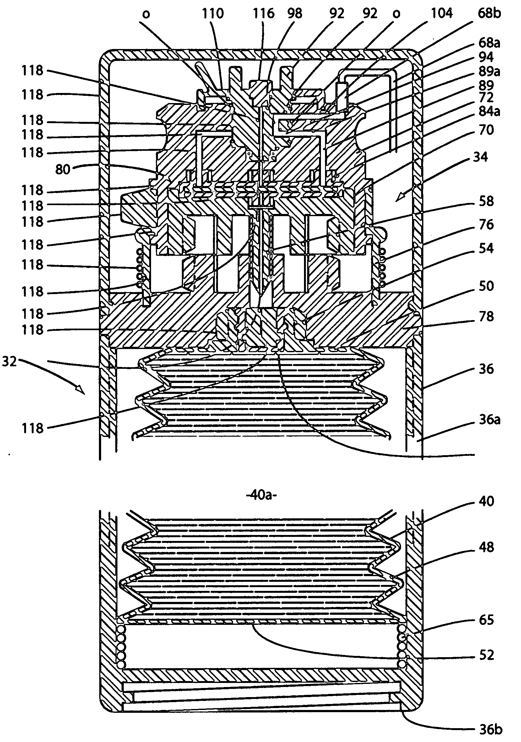
[0012]With the forgoing in mind, it is an object of the present invention to provide a compact, easy-to-use dispensing device that includes a uniquely configured fluid reservoir having a collapsible sidewall of progressively varying wall thickness that will deliver an injectable parenteral fluid contained within the fluid reservoir to the patient at a substantially constant flow rate.
[0019]Another object of the invention is to provide a fluid dispenser of the class described which is compact and lightweight, is easy for ambulatory patients to use, is fully disposable following its use and is extremely reliable in operation.
[0024]Another object of the invention is to provide a fluid dispenser of the character described that is of a simple construction that can be used in the field with a minimum amount of training.
[0025]Another object of the invention is to provide a fluid dispenser of the class described that will permit infusion therapy to be initiated quickly, at will, at point of care on the battlefield so that the attending medic or medical professional can more efficiently deal with triage situations in austere environments.
[0026]Another object of the invention is to provide a fluid dispenser that, due to its pre-filled and self-contained packaging, is inherently less likely to result in an unintentional medication error by the attending pharmacist, nurse or other medical clinician.
[0027]Another object of the invention is to provide a fluid dispenser as described in the preceding paragraphs that is easy and inexpensive to manufacture in large quantities.
Problems solved by technology
Such gravimetric methods are cumbersome, imprecise and require bed confinement of the patient.
Accordingly, the prior art devices are not well suited for use in those instances where the patient must be transported to a remote facility for treatment.
Drug infusion devices currently available can impede the timely administration of IV infusions in remote care settings.
Expensive electronic infusion pumps are not a practical field solution because of their weight, cumbersome size and power requirements.
Moreover, today's procedures for starting IV infusions on the battlefield are often dangerous because the attending medic must complete several time consuming steps.
Method used
Image
Click on the blue label to locate the original text in one second.
Reading with bidirectional positioning of images and text.
Examples
example 1
[0105]In Example 1, the delivery system design inputs consist of a particular spring (with a specified spring constant), a required container radius and a chamber pressure at which the dispenser will be operated. Therefore, a set of parameters defining the system can be set forth as follows:
[0107]The radius of the container at the position y1:r1=2.54 cm
[0108]The pressure at which the system will operate: ½ atm=5 N / cm2
With these values Equation (4) yields a value of y1 as:
y1=π(Pr12) / k=π(5)(2.54)2 / 5=20.3 cm
[0109]If we choose a second value of y, y2, to be the position where the force is ½ its value at y1 then we have using Equation 1 that y2=½ y1. So that:
[0111]In Example 2, the delivery system design inputs consist of a particular spring (with a specified spring constant), a required container volume and a chamber pressure at which the dispenser will be operated. Therefore, the set of parameters can be set forth as follows:
The radius of the container at position #1 can be obtained using Equation (5) and setting y=25.82...
PUM
Abstract
A compact, easy-to-use dispensing device that includes a uniquely configured unitary fluid container formed by a blow-fill-seal process. The container has a collapsible, tapered sidewall of progressively varying wall thickness that, upon being acted upon by an elastic member, will deliver an injectable parenteral fluid contained within the fluid reservoir to the patient at a substantially constant flow rate.
Description
BACKGROUND OF THE INVENTION[0001]1. Field of the Invention[0002]The present invention relates generally to fluid dispensing devices. More particularly, the invention concerns medicament dispensers for dispensing medicinal fluids to ambulatory patients at a precise rate.[0003]2. Discussion of the Prior Art[0004]A number of different types of medicament dispensers for dispensing medicaments to ambulatory patients have been suggested in the past. Many of the devices seek either to improve or to replace the traditional gravity flow and hypodermic syringe methods which have been the standard for delivery of liquid medicaments for many years.[0005]The prior art gravity flow methods typically involve the use of intravenous administration sets and the familiar flexible solution bag suspended above the patient. Such gravimetric methods are cumbersome, imprecise and require bed confinement of the patient. Periodic monitoring of the apparatus by the nurse or doctor is required to detect malfun...
Claims
Application Information
Patent Timeline
Application Date:The date an application was filed.
Publication Date:The date a patent or application was officially published.
First Publication Date:The earliest publication date of a patent with the same application number.
Issue Date:Publication date of the patent grant document.
PCT Entry Date:The Entry date of PCT National Phase.
Estimated Expiry Date:The statutory expiry date of a patent right according to the Patent Law, and it is the longest term of protection that the patent right can achieve without the termination of the patent right due to other reasons(Term extension factor has been taken into account ).
Invalid Date:Actual expiry date is based on effective date or publication date of legal transaction data of invalid patent.
IPC IPC(8): A61M37/00
CPCA61M35/003
InventorBIVIN, DONALD B.KRIESEL, JOSHUA W.KRIESEL, MARSHALL S.GLAVEE, GEORGE N.

