Flow restrictor

a flow restrictor and flow control technology, applied in the field of flow restrictors, can solve the problems of poor reliability of diaphragm regulators, high cost, and high cost of diaphragm regulators, and achieve the effects of reducing pressure, reducing pressure, and gradually reducing pressur

Active Publication Date: 2008-10-09
WOODSTREAM CORP
View PDF49 Cites 10 Cited by
  • Summary
  • Abstract
  • Description
  • Claims
  • Application Information

AI Technical Summary

Benefits of technology

[0010]In one embodiment, the flow restrictor is in the form of a long capillary that gradually reduces the pressure of the fluid. The head loss is caused by shear and frictional losses in the capillary. The length of the capillary provides that no abrupt disruptions in the flow are required to decrease the pressure. Instead, the pressure is gradually reduced over the length of the capillary. Thus, it is less likely that condensation is formed at a single point within the restrictor. Fu...

Problems solved by technology

However, such insect traps are very low pressure devices and require further pressure reduction.
A second flow restrictor is used because the diaphragm regulator has poor reliability at pressures much below 11 in H2O.
Many orifices used for precise pressure drop applications are very small.
Due to the size of the orifice, even very small quantities of precip...

Method used


Image

  • Flow restrictor
  • Flow restrictor
  • Flow restrictor

Examples


Embodiment Construction

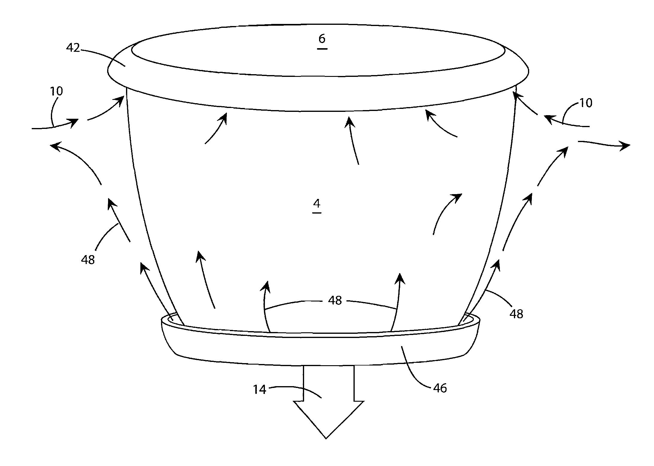
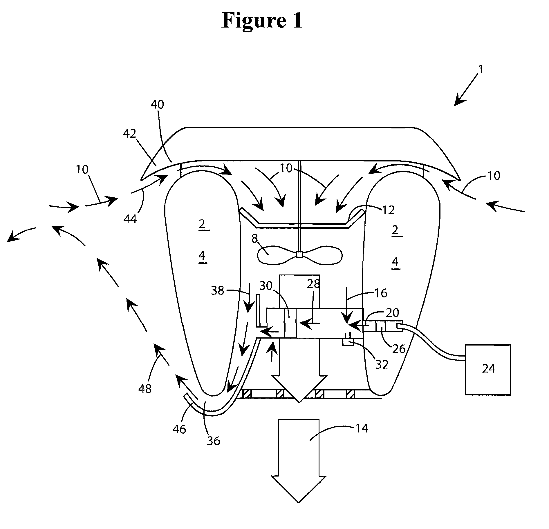
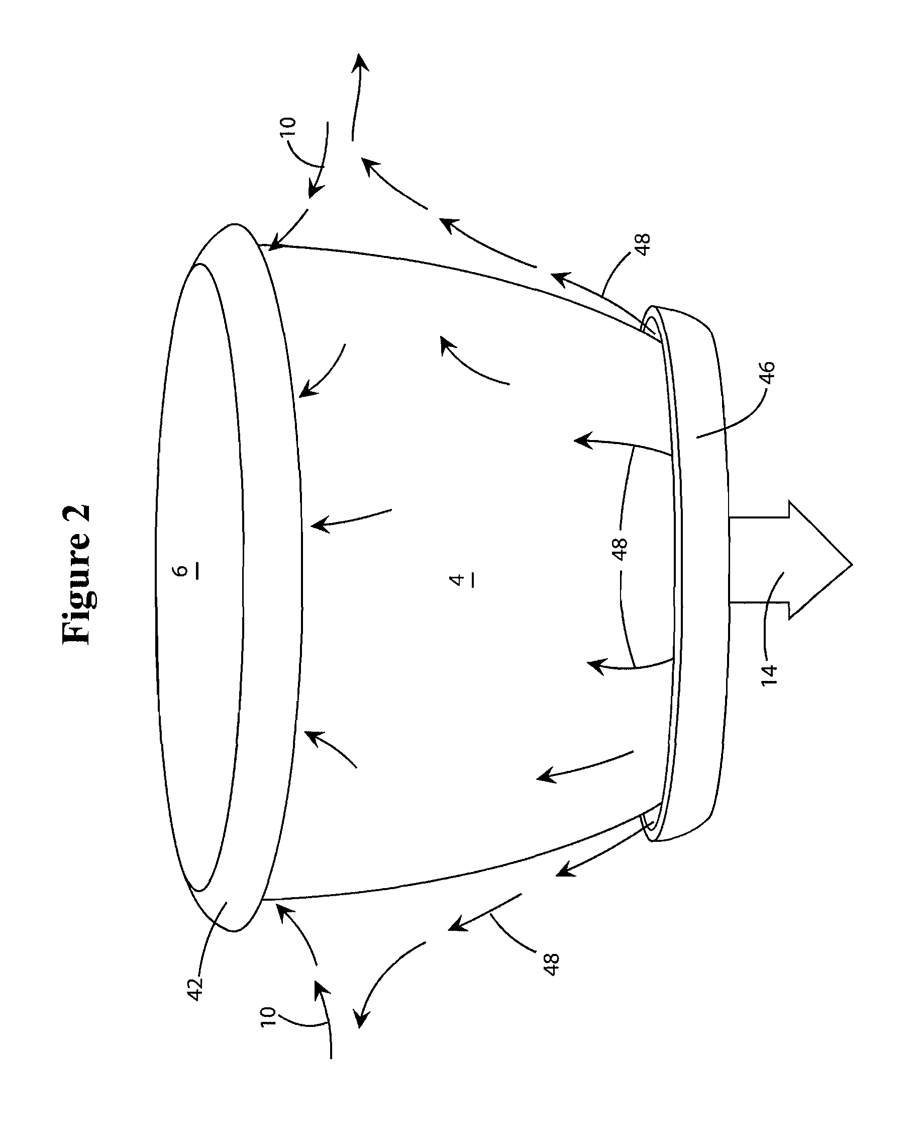
[0017]FIGS. 1 and 2 show an insect trap 1 incorporating an embodiment of a flow restrictor according to the present invention. The trap 1 includes a housing 2 formed of sidewalls 4 and a top 6. Within housing 2 is a suction device 8. The suction device 8 can be a rotational unit that is driven by a motor or an engine. For example, the suction device 8 can be a blower or a fan. The suction device 8 is shown diagrammatically in FIG. 1 as two rotor blades. The object of suction device 8 is to draw air through the CO2 trap 1 and any known method for doing so can be used.

[0018]Intake air 10 is pulled into the trap 1 at the top of the housing by suction device 8. Along with the intake air 10, insects are sucked into the trap. Once within the housing 2, the intake air 10 passes through a catch 12 wherein the insects contained in the air stream are captured. After passing through the suction device 8, or blower, the air is separated for various uses. Much of the air passes directly through ...


PUM


Abstract

A flow restrictor is provided to reduce pressure in the flow of a fluid, such as a hydrocarbon-based fuel. The flow restrictor takes the form of a capillary that is void of any abrupt flow disruptions. The flow restrictor may be used in place of an orifice and provides the advantage that it has a larger diameter than an orifice of similar function. Precipitation is less likely to form on the restrictor and any precipitation is less likely to have an adverse affect on performance.

Description

[0001]This application claims the benefit of U.S. Provisional Application 60 / 909,405, filed Mar. 30, 2007, the entire disclosure of which is incorporated by reference.FIELD OF THE INVENTION[0002]The present invention generally relates to a flow restrictor, and specifically relates to a flow restrictor that does not include abrupt flow disruptions and may be used with hydrocarbon-based gases.BACKGROUND OF THE INVENTION[0003]Flow restrictors, used for reducing pressure and regulating flow, are used in a vast number of different applications. For instance, CO2 insect traps, which produce CO2 from air and a combustible fuel, typically use two flow restrictors. A diaphragm regulator is first used to reduce the pressure of the combustible fuel from approximately 120 psi down to 11 in H2O (0.4 psi). However, such insect traps are very low pressure devices and require further pressure reduction. A second flow restrictor is used because the diaphragm regulator has poor reliability at pressur...

Claims


Application Information

Patent Timeline
IPC IPC(8): A01M1/20F16L55/027
CPCA01M1/023A01M1/06G05D7/0186
Inventor SCHINAZI, ALANZITNICK, DAVIDPISHDADIAN, HAMIDVIEIRA, MICHAEL C.
Owner WOODSTREAM CORP
Why Eureka
Try Eureka