Lubrication System for Touchdown Bearings of a Magnetic Bearing Compressor

Active Publication Date: 2008-10-09
CARRIER CORP
View PDF18 Cites 21 Cited by
  • Summary
  • Abstract
  • Description
  • Claims
  • Application Information

AI Technical Summary

Benefits of technology

[0006]The compressor includes an impeller, a diffuser, a main motor rotor, a main motor stator and a magnetic bearing housed in a compressor housing. The main motor stator drives the main motor rotor to rotate through a magnetic field, driving a shaft to reduce a volume of the refrigerant received in compression chambers of the compressor and compress the refrigerant to a high pressure.
[0007]A radial touchdown bearing and an axial touchdown bearing protect the rotor during power shutdown of the compressor and protect the magnetic bearing from failure. The radial touchdown bearin

Problems solved by technology

A drawback to ceramic ball bearings and s

Method used


Image

  • Lubrication System for Touchdown Bearings of a Magnetic Bearing Compressor
  • Lubrication System for Touchdown Bearings of a Magnetic Bearing Compressor
  • Lubrication System for Touchdown Bearings of a Magnetic Bearing Compressor

Examples


Embodiment Construction

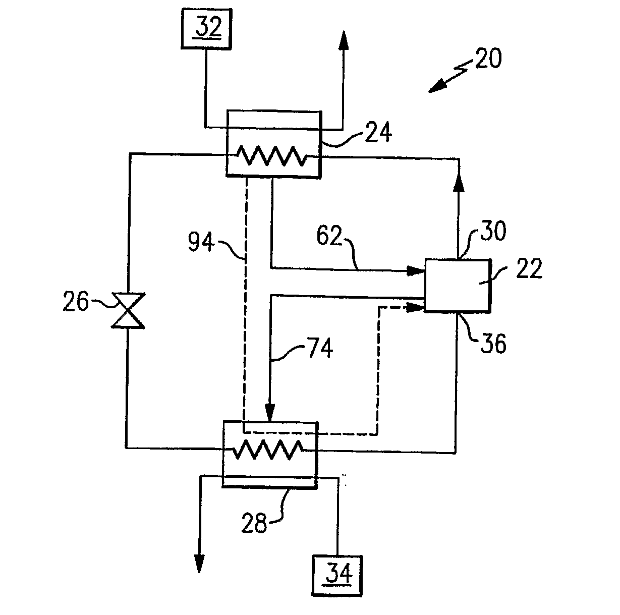
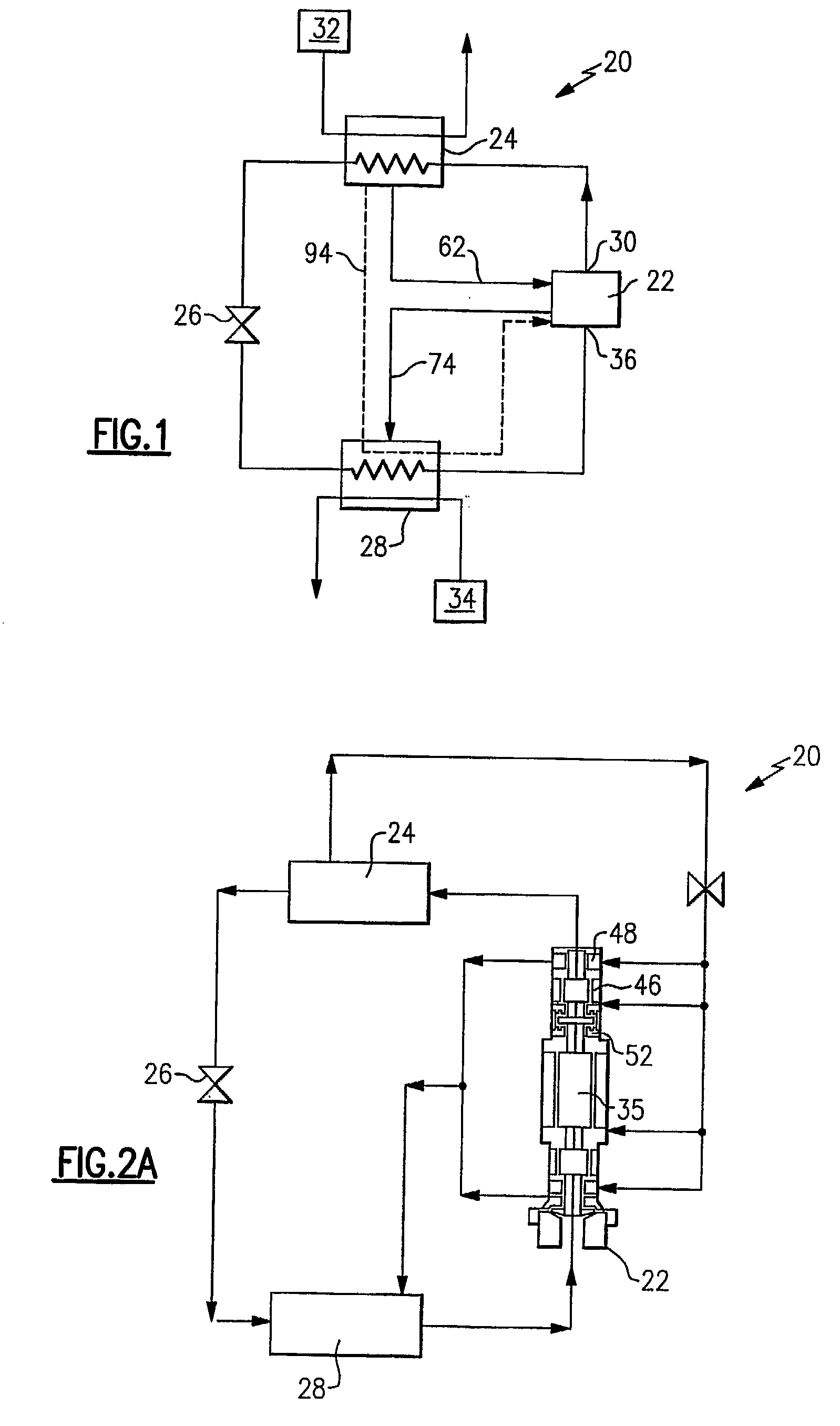
[0017]FIG. 1 illustrates an example vapor compression system 20 including a compressor 22, a condenser 24, an expansion device 26 and an evaporator 28. Refrigerant circulates though the closed circuit vapor compression system 20. The refrigerant exits the compressor 22 through a discharge port 30 at a high pressure and a high enthalpy. The compressor 22 can be a screw compressor, a rotary compressor, a turbo compressor, or any type of compressor.

[0018]The refrigerant then flows through the condenser 24. An external fluid medium 32, such as water or air, flows through the condenser 24 and exchanges heat with the refrigerant flowing through the condenser 24. The pressure of the refrigerant in the condenser 24 is typically approximately 100 psi. The refrigerant rejects heat to the external fluid medium 32 and exits the condenser 24 at a relatively low enthalpy and a high pressure in a liquid state.

[0019]The refrigerant is then expanded by the expansion device 26, reducing the pressure ...


PUM


Abstract

A vapor compression system includes a compressor, a condenser, an expansion device and an evaporator. Refrigerant circulates though the closed circuit vapor compression system. Touchdown bearings protect a rotor during power shutdown of the compressor. Liquid refrigerant from the condenser flows along a supply line and lubricates the touchdown bearings. The refrigerant from the touchdown bearings is discharged through an outlet and flows along a discharge line to the evaporator.

Description

BACKGROUND OF THE INVENTION[0001]The present invention relates generally to a bearing lubrication system that lubricates a touchdown bearing of a compressor equipped with magnetic bearings with liquid refrigerant from a condenser.[0002]A vapor compression system includes a compressor, a condenser, an expansion device and an evaporator. Refrigerant circulates though the closed circuit vapor compression system. The refrigerant exits the compressor through a discharge port at a high pressure and a high enthalpy. The refrigerant then flows through the condenser at a high pressure and rejects heat to an external fluid medium. The refrigerant then flows through the expansion device, which expands the refrigerant to a low pressure. After expansion, the refrigerant flows through the evaporator and absorbs heat from another external fluid medium. The refrigerant then re-enters the compressor through a suction port, completing the cycle.[0003]The compressor includes an impeller, a diffuser, a...

Claims


Application Information

Patent Timeline
IPC IPC(8): F25B43/02F25B1/00F25B41/00
CPCF04D29/058F04D29/059F04D29/063F16C33/1045F16C37/00F16C39/02F25B31/002F25B2500/06F25B2500/27F16C32/0442F16C33/109F16C2362/52
Inventor SISHTLA, VISHNU M.
Owner CARRIER CORP
Why Eureka
Try Eureka