Heat storage tank

a technology of heat storage tank and heat exchanger, which is applied in the direction of indirect heat exchanger, machine/engine, light and heating apparatus, etc., can solve the problems of increasing cost and achieve the effect of increasing cos

Inactive Publication Date: 2008-10-09
DENSO CORP
View PDF1 Cites 13 Cited by
  • Summary
  • Abstract
  • Description
  • Claims
  • Application Information

AI Technical Summary

Benefits of technology

[0006]However, the heat storage tank described above requires two tanks in

Problems solved by technology

However, the heat storage tank described above requires two tanks inclu

Method used


Image

  • Heat storage tank
  • Heat storage tank
  • Heat storage tank

Examples


Embodiment Construction

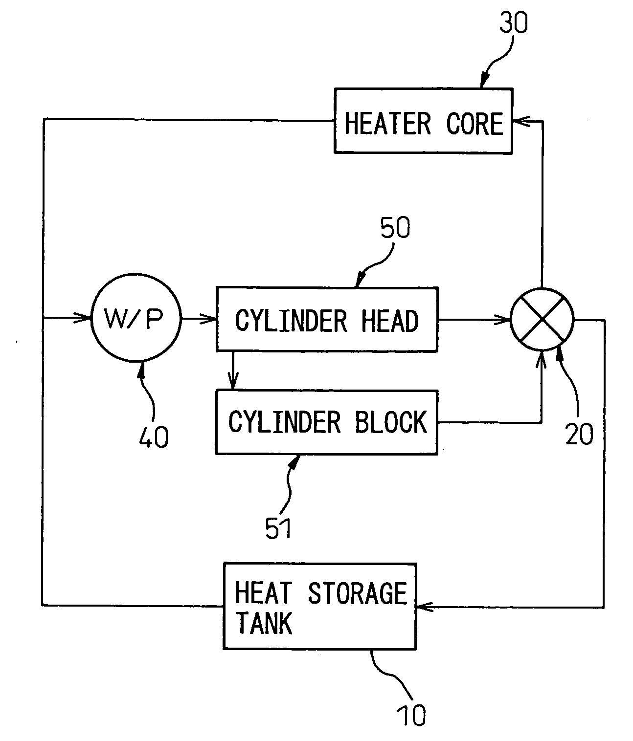
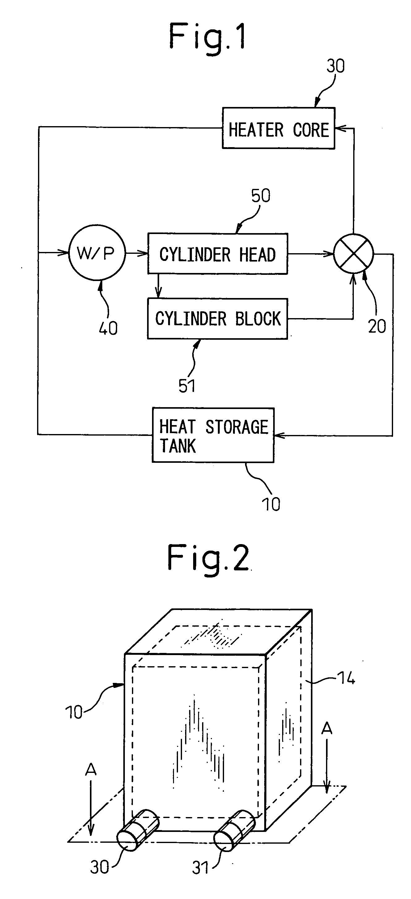
[0025]FIG. 1 shows a configuration of the cooling water circuit using the vehicle heat storage tank according to an embodiment of the invention.

[0026]The cooling water circuit includes a heat storage tank 10, a four-way valve 20, a heater core 30 and an electrically-operated pump 40. Heat storage tank 10 is for insulating and storing the engine cooling water. Four-way valve 20 connects the outlet side of one of a cylinder head 50 and a cylinder block 51 of the engine to the inlet side of at least one of heater core 30 and heat storage tank 10.

[0027]Heater core 30, which makes up a vehicle air conditioning system, is a heat exchanger for heating the air with the engine cooling water. Electrically-operated pump 40 is a circulation pump for supplying the engine cooling water toward the inlet side of each of cylinder head 50 and cylinder block 51.

[0028]In the cooling water circuit, a connection is established only between the outlet side of cylinder block 51 and the inlet side of heat s...


PUM


Abstract

A heat storage tank 10 comprises a plastic container 11 for storing engine cooling water, an inflow pipe 30 and an outflow pipe 31 communicating with the interior of plastic container 11 and formed to project from plastic container 11, and a heat-insulating layer 13 arranged to cover the whole periphery of plastic container 11 to insulate the heat of the engine cooling water in plastic container 11.
Heat-insulating layer 13 is arranged to cover the roots of pipes 30, 31. Therefore, the heat radiation of the engine cooling water from the bases of pipes 30, 31 can be suppressed thereby preventing a reduction in heat insulation effect.

Description

BACKGROUND OF THE INVENTION[0001]1. Field of the Invention[0002]This invention relates to a heat storage tank for storing and insulating a liquid.[0003]2. Description of the Related Art[0004]A cooling system for promoting the warm-up of a water-cooled internal combustion engine of an automotive vehicle has conventionally been proposed in which a heat storage tank for storing and insulating the engine cooling water flowing out of the water-cooled engine is arranged in the cooling water circuit and the high-temperature cooling water stored in the heat storage tank is introduced to the engine to accelerate engine warm-up. This makes it possible to utilize the extraneous heat of the engine effectively and reduce the fuel consumption from the overall viewpoint of the vehicle operation.[0005]Generally, the heat storage tank has a double heat-insulating structure including an inner cylindrical tank of stainless steel making up a heat storage tank body and an outer cylindrical tank of stain...

Claims


Application Information

Patent Timeline
IPC IPC(8): F01P11/02
CPCF01P2003/027F01P2011/205F01P2060/08F28D20/0034Y02E60/142Y02E60/14
Inventor TOYOSHIMA, TAKASHIMIYATA, YOSHIO
Owner DENSO CORP
Why Eureka
Try Eureka