Magnetic bearing spindle device for machine tool

a technology of magnetic bearing and machine tool, which is applied in the direction of magnetic bearings, manufacturing tools, mechanical equipment, etc., can solve the problems of increasing the torsional load of the ball screw, the limit of coping with requests, and the increase of the rotation number of the motor, so as to achieve high speed and reduce production costs. , the effect of high precision

Inactive Publication Date: 2008-10-09
JTEKT CORP
View PDF7 Cites 10 Cited by
  • Summary
  • Abstract
  • Description
  • Claims
  • Application Information

AI Technical Summary

Benefits of technology

[0021]According to the invention, positioning of the main shaft can be performed at high speed and with high precision while the production cost is depressed.

Problems solved by technology

However, because problems such as occurrence of vibration and noise, rise of temperature, increase of thermal expansion, etc. are concerned, there is a limit in coping with the requests by increasing the rotation number of the motor.
However, in this case, as the lead of the ball screw becomes larger, torsional load on the ball screw increases, and it is concerned that torsional vibration and positioning error may occur accordingly.
In case where the ball screw mechanism is employed as the feeding mechanism in this manner, there has been a limit in positioning the magnetic bearing spindle device at high speed and with high precision.
However, the feeding mechanism employing the linear motor as the drive source tends to become large-sized and expensive in principle, as the feeding speed and positioning precision are enhanced.
Therefore, there is a problem that it is difficult to take a balance between performances of the magnetic bearing spindle device such as the feeding speed and the positioning precision which have been required and the production cost.

Method used


Image

  • Magnetic bearing spindle device for machine tool
  • Magnetic bearing spindle device for machine tool
  • Magnetic bearing spindle device for machine tool

Examples


Embodiment Construction

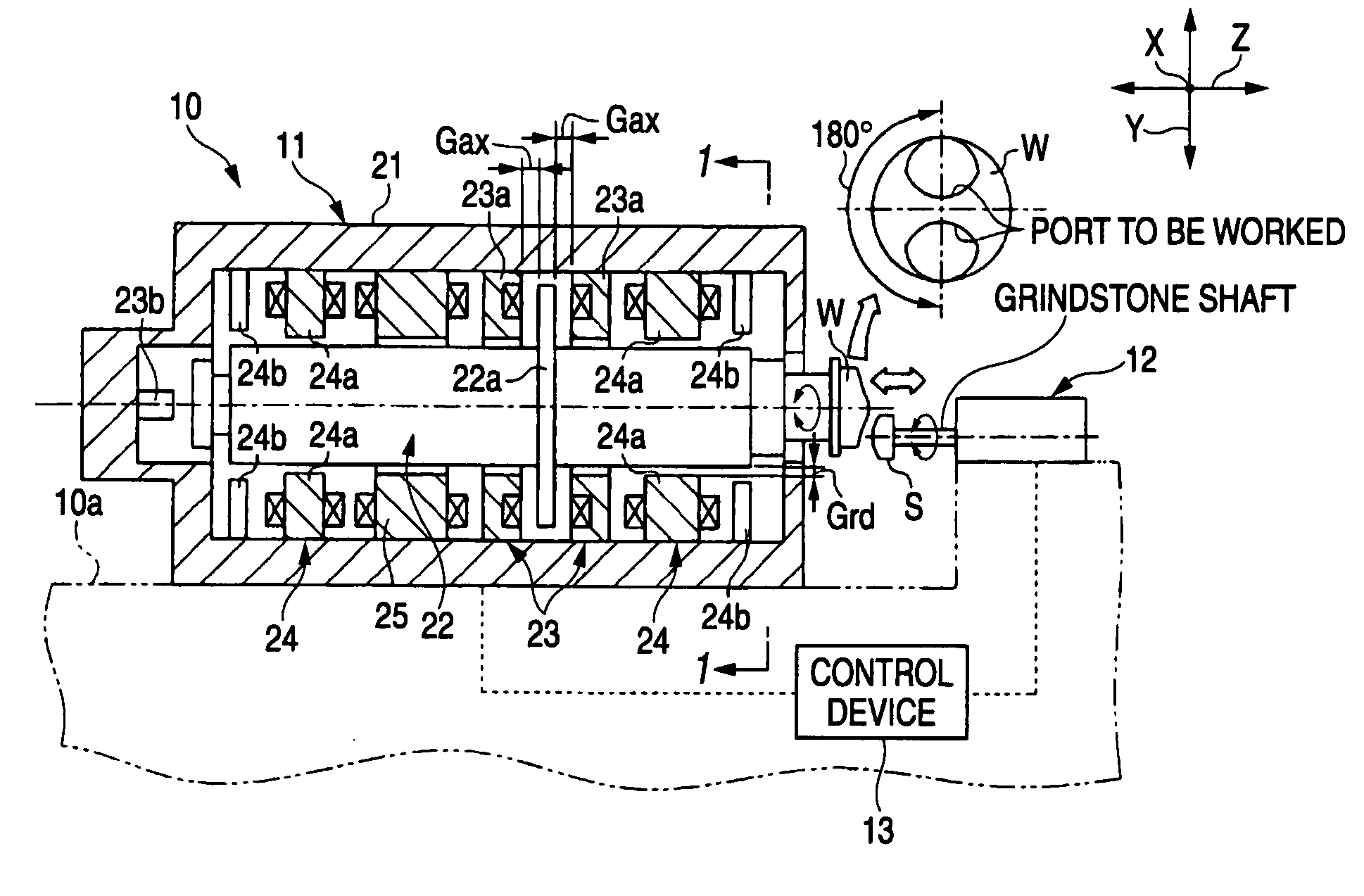
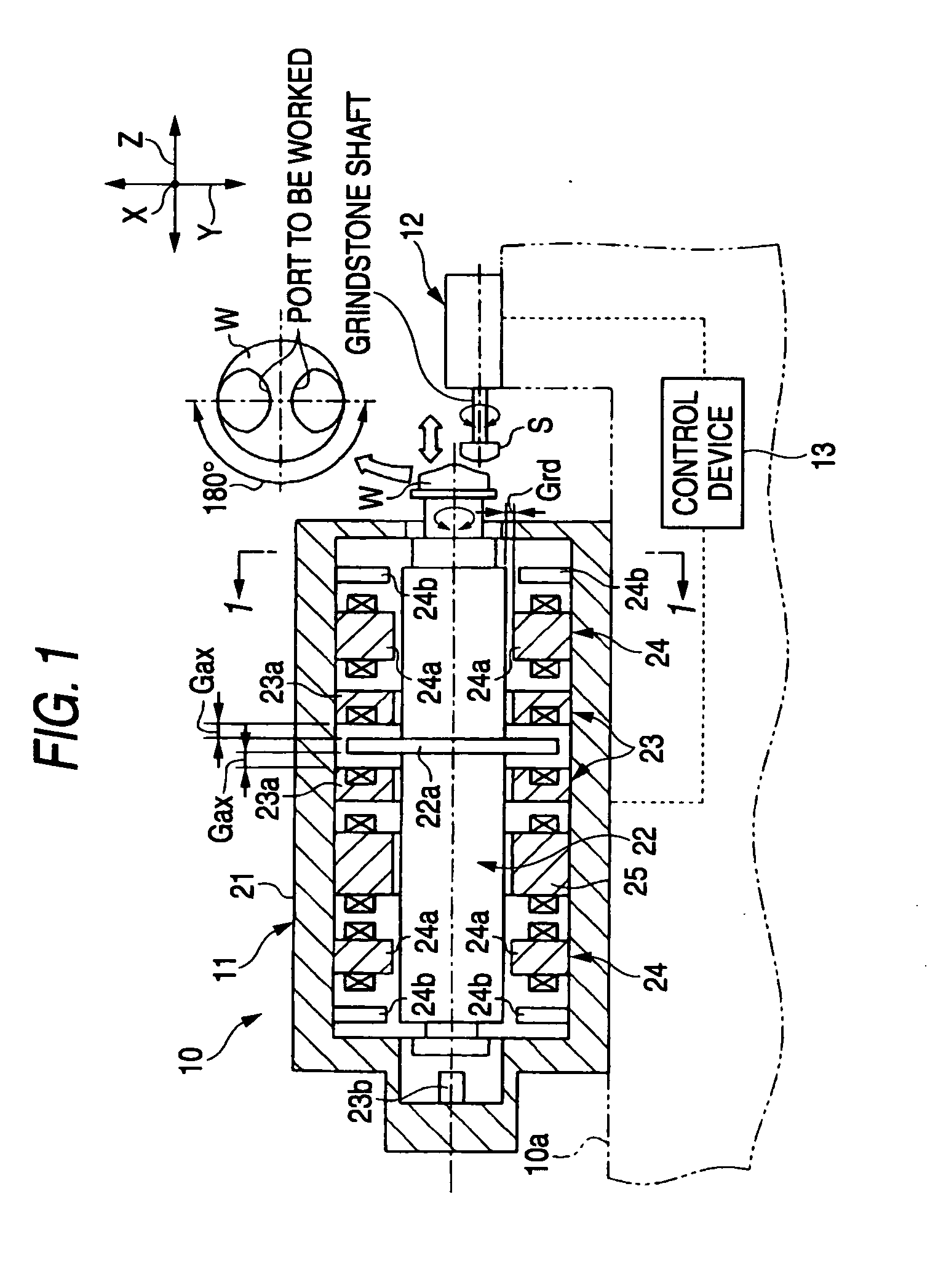
[0028]Now, referring to FIGS. 1 to 3, the invention will be described by way of an embodiment which is applied to a magnetic bearing spindle device to be mounted on a grinding apparatus as a machine tool. In this embodiment, the grinding apparatus conducts rough grinding of a non-spherical lens.

[0029]As shown in FIG. 1, a magnetic bearing spindle device 11 which supports a work W so as to rotate, and a grindstone shaft spindle device 12 which supports a grindstone S, as a working tool, in a rotated state are disposed on an upper surface of a chassis 10a of a grinding apparatus 10. The grinding apparatus 10 is further provided with a control device 13 for controlling the magnetic bearing spindle device 11 and the grindstone shaft spindle device 12. The work W supported by the magnetic bearing spindle device 11 is rotated by 180 degree at a determined time interval, and pressed against the grindstone S which is held by the grindstone shaft spindle device 12 in a rotated state. In this...


PUM

PropertyMeasurementUnit
displacement detectoraaaaaaaaaa
speedaaaaaaaaaa
repulsive forceaaaaaaaaaa

Abstract

The control device displaces the main shaft in the axial direction and in the radial direction within the range of the gap between the rib member of the main shaft and the axial magnetic bearing and the gap between the main shaft and the radial magnetic bearings, by controlling the attraction forces of the axial electromagnets and the radial electromagnets, whereby the main shaft can be positioned. By controlling the axial magnetic. bearing and the radial magnetic bearings, it becomes possible to freely displace only the main shaft in the axial direction and in the radial direction, and therefore, the main shaft can be positioned at high speed and with high precision. Moreover, there is no necessity of providing the feeding mechanism in which the ball screw mechanism and linear motor etc. are employed for the purpose of displacing the magnetic bearing spindle device, and hence, reduction of the production cost for the grinding apparatus can be achieved.

Description

BACKGROUND OF THE INVENTION[0001]The present invention relates to a magnetic bearing spindle device for a machine tool.[0002]Conventionally, in a machine tool such as a grinding apparatus, a cutting apparatus, a machining center, etc., use of a magnetic bearing spindle device which supports a main shaft (a spindle) by means of a magnetic bearing in a non-contact manner, for the purpose of rotating the main shaft at high speed, has increased more and more. As the magnetic bearing spindle device for this purpose, a magnetic bearing spindle device in which the main shaft is supported in a non-contact manner by means of a set of axial magnetic bearing and two sets of radial magnetic bearings, as disclosed in JP-A-10-29101, for example, has been generally used.[0003]In order to conduct complicated machine working, it is necessary to displace the magnetic bearing spindle device itself to which a work or a working tool is attached, and therefore, the magnetic bearing spindle device is so p...

Claims


Application Information

Patent Timeline
Patent Type & Authority Applications(United States)
IPC IPC(8): H02K7/09
CPCB23Q1/70B23Q17/2258F16C32/044F16C2322/39H02K7/09
Inventor KUBO, ATSUSHI
Owner JTEKT CORP
Why Eureka
Try Eureka