Lighting Device and a Lighting Method for a High Pressure Discharge Lamp

Inactive Publication Date: 2008-10-09
SEIKO EPSON CORP
View PDF0 Cites 4 Cited by
  • Summary
  • Abstract
  • Description
  • Claims
  • Application Information

AI Technical Summary

Benefits of technology

[0025]According to the invention of the present application, since the duty ratio before and after polarity inversion of the short period current and the standard period current supplied as the lamp current can be set optionally, by setting the duty ratio such that the electrode at the lower temperature operates as the anode for a longer time, the temperature for each of the electrodes can be made substantially equal by rising the electrode temperature at the lower temperature thereby capable of eliminating the movement of arc spot due to temperature difference and suppressing flickering.
[0026]In this case, by using a high pressure discharge lamp of a type identical with the high pressure discharge lamp to be lit and previously measuring an optimal value of minimizing the flickering for the ratio of the time at which the electrode operates as an anode and as a cathode, since the duty ratio of the lamp current can be set in accordance with the optimal value, flickering can be suppressed effectively by one type of a lighting device for any high pressure discharge lamp without designing the lighting device on every type of the high pressure discharge lamps.
[0027]Further, as described in claim 3, since it can be formed as a ramp wave of gradually increasing or decreasing the current value before and / or after the polarity inversion of the short period current, this can be used also for a high pressure discharge lamp capable of suppressing flickering more effectively by the use of the ramp way.
[0028]Further, in a case where the current value before and / or after the polarity inversion of the short period current is set higher than the current value of the standard period current as described in claim 4 and, particularly, in a case where the current value of the short period current is set to 1.2 times or more and 5 times or less the current value of the standard period current, since this is most effective for warming the arc spot portion of the electrode, the arc spot becomes less moving and flickering can be prevented more effectively.
[0029]As described in claim 6, in a case where the period of the standard period current is set to 1 / 60 sec or more, flickering by blinking upon polarity inversion is no more visible and, in a case where it is 1 / 500 sec or less, the acoustic resonance phenomenon does not occur.
[0030]Further, in a case where the period of the short period current set to ¼ times or more the standard period, since the load on the electrode does not increase so much even in a case of setting current value thereof to higher than the standard period current, this does not result in a problem of violent abrasion of the electrode.

Problems solved by technology

However, in the existent high pressure discharge lamp lighting device of lighting only by the low frequency rectangular wave, since arc means can not be controlled in a super-high pressure mercury lamp, the amount of light entering the light receiving portion changes greatly by the arc movement and, when used to a liquid crystal projector, it causes a problem that the change of the screen illuminance increases to result in flickering on the screen.
Particularly, along with reduction in the size and the weight of liquid crystal projectors, reduction in the size and increase in the illuminance have been progressed for the reflection mirror of the light source and the size of the liquid crystal device as the photoreceiving portion is also reduced correspondingly, so that this results in a significant effect of flickering on the even for an identical amount of arc movement.
However, high pressure discharge lamps or super-high pressure discharge lamps having a function of adding high value such as a light control function and an optional power fluctuation change have been manufactured recently, and it has been found that flickering can not be controlled effectively in such high pressure discharge lamps even when the lamp current as described above is supplied.
As a result, the arc spot is not fixed tending to cause flickering, as well as a difference is caused to the amount of deformation due to deposition of metal vapors to the electrode surface or the abrasion of the electrode to result in the difference for the distance between the electrodes, thereby resulting in a problem that the control for the arc spot is made more difficult in a case of AC lighting.

Method used


Image

  • Lighting Device and a Lighting Method for a High Pressure Discharge Lamp
  • Lighting Device and a Lighting Method for a High Pressure Discharge Lamp
  • Lighting Device and a Lighting Method for a High Pressure Discharge Lamp

Examples


embodiment 1

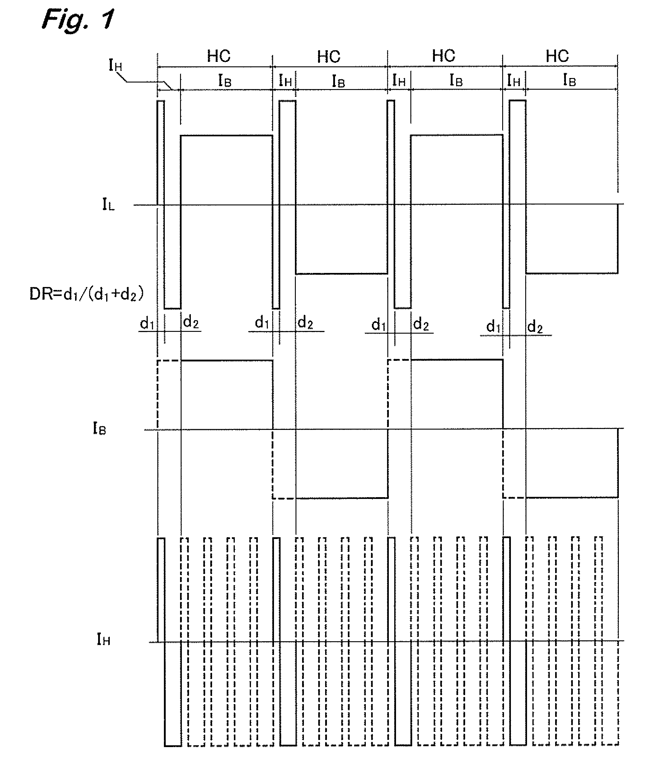
[0035]FIG. 1 shows waveforms of a lamp current IL, a standard period circuit IB, and a short period current IH supplied to a high pressure discharge lamp.

[0036]Then, the lamp current IL comprises a standard period current IB having a period of 1 / 500 sec or more and 1 / 60 sec or less supplied at a predetermined standard period, and a short period current IH having a period set to 1 / 30 times or more and ¼ times or less thereof. On every start of the one-half period HC upon inversion of the polarity for the standard period current IB, a short period current IH inverted for the polarity from an identical polarity to an opposite polarity is supplied for one period instead of the standard period current IB.

[0037]The lighting period of the standard period current IB is set to 1 / 500 sec or more and 1 / 60 sec or less, because blinking caused upon polarity inversion becomes visible to result in flickering in a case where it exceeds 1 / 60 sec, and acoustic resonance phenomenon occurs when it is l...

embodiment 2

[0096]FIG. 8 shows waveforms for a lamp current IL, a standard period current IB, and a short period current IH supplied to the high pressure discharge lamp, and the lamp current IL is formed by supplying a standard period current IB comprising a rectangular wave at a frequency of 1 / 500 sec or more and 1 / 60 sec or less that oscillates at the predetermined standard period TB and a short period current IH shown in FIG. 8 having the period TH set to 1 / 30 times or more and ¼ times or less thereof alternately each for 1-period.

[0097]The standard period TB of the standard period current IB is set to 1 / 500 sec or more and 1 / 60 sec or less, because blinking caused upon polarity inversion becomes visible to result in flickering in a case where it exceeds 1 / 60 sec, and acoustic resonance phenomenon occurs when it is set to less than 1 / 50.

[0098]Further, the period TH for the short period current IH is set to 1 / 30 or more and ¼ times or less the standard period current IB, because excess load e...


PUM


Abstract

Even in a high pressure discharge lamp causing temperature difference between electrodes when an AC current is supplied, the temperature difference is eliminated to suppress the arc movement, thereby suppressing flickering caused thereby during stable lighting.The lamp current is formed into a current waveform including a standard period current supplied at a predetermined standard period and a short period current of a period shorter than the same and, on every one-half period of the standard period current, formed into a current waveform by supplying the short period current inverting the polarity from the identical polarity to the opposite polarity in the next one-half period for 1 period, in which the duty ratio before and after the polarity inversion of the short period current and the duty ratio before and after the polarity inversion side can be decided automatically by the duty ratio.

Description

TECHNICAL FIELD [0001]The present invention concerns a lighting device and a lighting method for a high pressure discharge lamp by supplying an AC lamp current to light up a high pressure discharge lamp.BACKGROUND ART [0002]A high pressure discharge lamp lighting device for use in a light source device for back light, for example, of a liquid crystal projector is adapted to light up the lamp by converting a current supplied from a DC power source to a rectangular current at a predetermined lighting frequency thereby switching the lighting polarity of the high pressure discharge lamp.[0003]FIG. 13 shows an existent lighting device 31 for a high pressure discharge lamp in which a DC power outputted from a DC power source 2 is inputted to a chopper circuit 3 and a control circuit IC converted into an appropriate DC current by controlling the duty ratio of a switching device 4 by a PWM control circuit 32 is inputted to a full-bridge circuit 5.[0004]In the full-bridge circuit 5, paired t...

Claims


Application Information

Patent Timeline
IPC IPC(8): H05B41/14H05B41/292
CPCH05B41/2883H05B41/2928Y02B20/208Y02B20/00H05B41/24H05B41/28H05B41/292
Inventor KIKUCHI, SEIJI
Owner SEIKO EPSON CORP
Why Eureka
Try Eureka