Method of producing major diameter TbDyFe-base alloy directionally solidified crystal

A directional solidification, large-diameter technology, applied in the direction of self-solidification, crystal growth, chemical instruments and methods, etc., can solve the problem of destroying the continuity and stability of crystal growth, the effect of mechanical shock in the melting zone, and the mother bar and the induction coil. Loss of matching and other problems, to achieve the effect of eliminating vibration, suppressing the tendency of cracks, and saving energy

Inactive Publication Date: 2007-02-28
李碚
View PDF7 Cites 4 Cited by
  • Summary
  • Abstract
  • Description
  • Claims
  • Application Information

AI Technical Summary

Problems solved by technology

[0007] 2. Under the condition of heating with the induction coil, when the directional solidification process is close to the end and the end of the mother rod is heated, the coupling between the mother rod and the induction coil will lose matching due to the small load
This is because the mechanical vibration of the mother rod is more intense during the pulling process; the power of the heating electromagnetic field increases, and the electromagnetic field of the induction coil intensifies the disturbance of the melting zone; the rod above the melting zone cracks to form falling blocks and uneven melting. The rod above the melting zone collapses, thereby increasing the mechanical impact on the melting zone, which will destroy the continuity and stability of crystal growth
[0009] 4. The internal stress generated during the solidification process will cause the material to crack
[0010] 5. Low efficiency and high energy consumption

Method used


Image

  • Method of producing major diameter TbDyFe-base alloy directionally solidified crystal
  • Method of producing major diameter TbDyFe-base alloy directionally solidified crystal
  • Method of producing major diameter TbDyFe-base alloy directionally solidified crystal

Examples


Embodiment 1

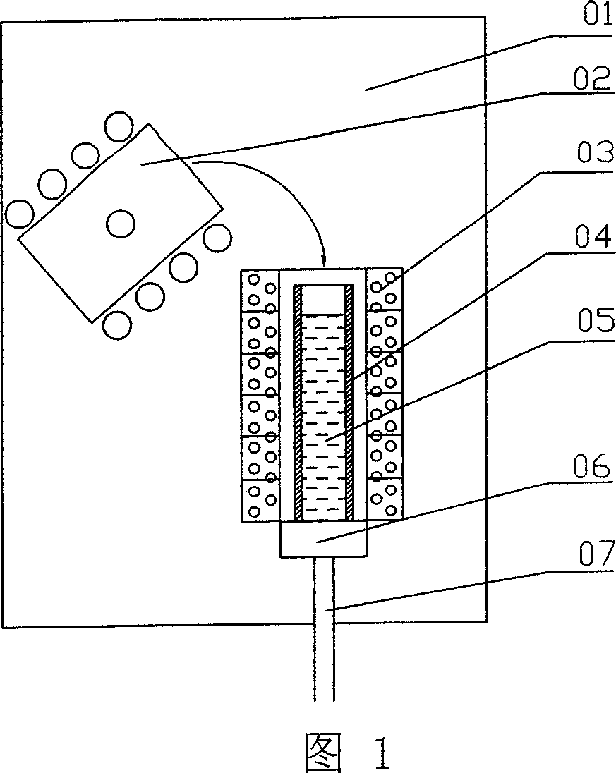
[0052] Utilize a device belonging to the basic structure, as shown in Figure 1. The equipment is equipped with a 500kW intermediate frequency induction power supply, equipped with a water-cooled copper crucible 02, and can melt 25kg of Tb with suspension melting technology 0.3 Dy 0.7 Fe 1.95 alloy. The structure and operation of the smelting part of the equipment are basically the same as those introduced in the applicant's patent ZL01274217.1. Next to the crucible 02 are vertically arranged heater groups stacked up and down, each heater 03 constitutes a heating layer, and the heating temperature of each layer can be independently measured and controlled. The heater group consists of 6 molybdenum wire heaters 03 stacked up and down. A quartz tube mold 04 with an inner diameter of 103mm and a height of about 400mm is placed vertically in the center of the heater group. The lower end of the mold tube is installed on the copper water cooling head 06, and the tubular mold 04 i...

Embodiment 2

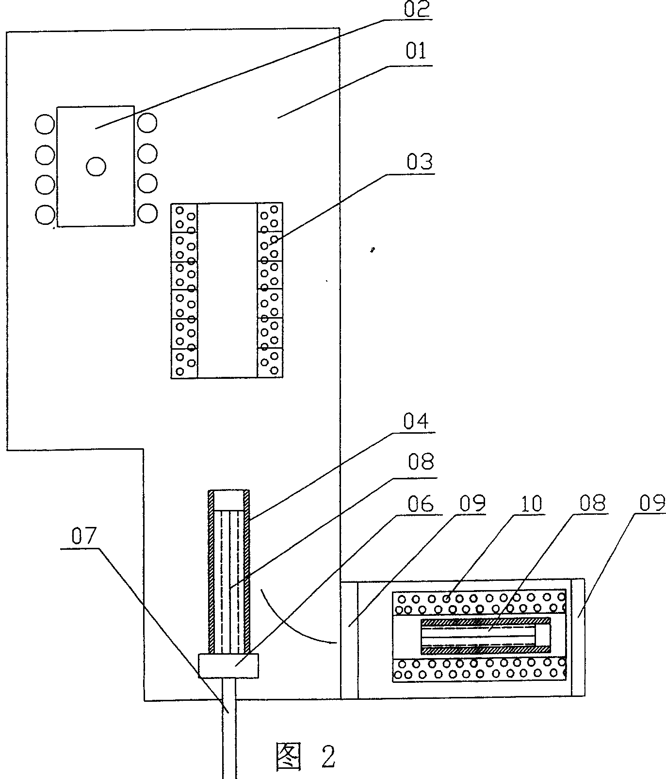
[0055] As shown in Figure 2, the heat treatment furnace 10 can be isolated from the vacuum-argon filling system of the furnace body 01 by the left sealed door 09, so after the directional solidification process is completed, the crystal rod 08 is sent to the treatment furnace 10 in the same furnace body , and then close the left airtight door 09 to isolate the argon atmosphere in the processing furnace 10 from the furnace body. At this time, the smelting furnace can be opened, the hearth is cleaned, and the charge of the next furnace is loaded, and the second furnace is vacuumed, smelted and directional solidified. During the 4.5 hours in the second furnace, the crystal rods in the first furnace completed the slow cooling and heat treatment process in the closed heat treatment furnace 10 . The heat treatment furnace 10 is kept in a state of being isolated from the furnace body 01, and the airtight door 09 on the right side is opened, and the crystal rod 08 is taken out. After...

Embodiment 3

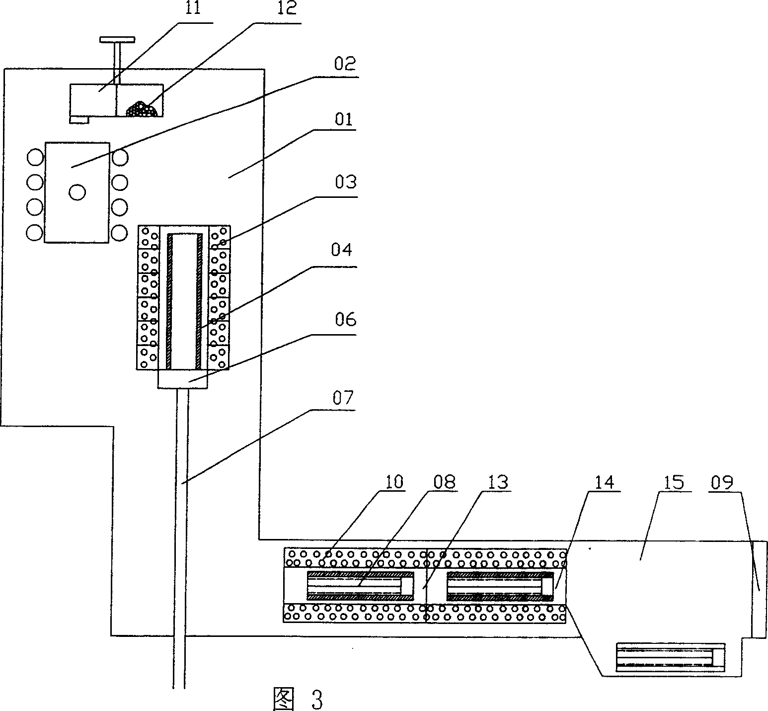
[0057] Batch method, as shown in Figure 3. : the one, feeder 11 compartments; the 2nd, heat treatment furnace 10 is lengthened on the basis of above embodiment 2 treatment furnace but different body of furnace 01 is isolated, and heat treatment section 13, slow cooling section 14 and storage section 15 are set successively in it. After a number of furnace charges 12 are loaded into each compartment of the feeder 11, the furnace body 01 is closed, vacuumed and filled with argon, and then the first furnace charge is added to the crucible 02, and the melting process is completed in one hour. After the alloy liquid 05 is injected into the mold 04, the second batch of charge is added to the crucible 02 without turning on the furnace, and after waiting for 0.5 hours, it takes 1 hour for the second furnace to smelt; at the same time, the alloy in the mold 04 Liquid 05 takes 1.5 hours to complete directional solidification, and this first crystal rod 08 is sent into heat treatment fur...


PUM

PropertyMeasurementUnit
diameteraaaaaaaaaa
diameteraaaaaaaaaa
diameteraaaaaaaaaa

Abstract

The invention relates the technology for producing directional freeze TbDyFe magnetostriction alloy, comprising the following steps: smelting master alloy with copper cold-crucible in vacuum induction suspending smelting furnace; installing ring heater out of die, every heater being a ring heating layer, the temperature being controlled and measured separately, opening heaters, making the temperature above the fusing point of alloy; putting the molten liquid into tubular die, bottom-up reducing the temperature of heater, making the alloy liquid freeze, and then carrying out heat treatment at the cooling course. The invention has the advantages of high productivity, low cost and mass production.

Description

technical field [0001] The invention belongs to the technology of preparing directionally solidified TbDyFe-based magnetostrictive alloy. Background technique [0002] Rare earth giant magnetostrictive alloy is a kind of RFe that can generate large strain in magnetic field 2 Compounds (R refers to rare earth elements), mainly including (TbDy)Fe 2 Alloys and SmFe 2 Two types of alloys, the most commonly used is Tb 0.3 Dy 0.7 Fe 1.95 alloy (hereinafter referred to as RE-GMM). RE-GMM generally uses a vacuum non-consumable electric arc furnace to melt the master alloy, and processes it in a vacuum directional solidification equipment to make the alloy form a directional crystal structure with axial orientation, and then perform heat treatment. [0003] Regarding the directional solidification treatment of RE-GMM, the Czochralski technique was used to prepare single crystals in the early stage. In 1981, Savage et al adopted the Bridgeman technology in U.S. Patent No. 4,308...

Claims


Application Information

Patent Timeline
Patent Type & Authority Applications(China)
IPC IPC(8): C30B11/00C22C38/00
Inventor 李碚
Owner 李碚
Why Eureka
Try Eureka