Inductive load sensor for dimmer circuit

Inactive Publication Date: 2008-10-09
ENOCEAN
View PDF7 Cites 20 Cited by
  • Summary
  • Abstract
  • Description
  • Claims
  • Application Information

AI Technical Summary

Benefits of technology

[0006]In a disclosed embodiment of this invention, an inductive load sensor for a dimmer circuit identifies the presence of an inductive load by voltage spikes. If an inductive load is sensed, the sensor stops the dimming of the load such that the power delivered to the inductive load is full “on” when the switch is turned on, or full “off” when the switch is off.

Problems solved by technology

One problem with such electrical outlets is that there is no way to guarantee a user will only utilize the electrical outlet for a light.
When these loads are inductive, there can be s

Method used


Image

  • Inductive load sensor for dimmer circuit
  • Inductive load sensor for dimmer circuit
  • Inductive load sensor for dimmer circuit

Examples


Example

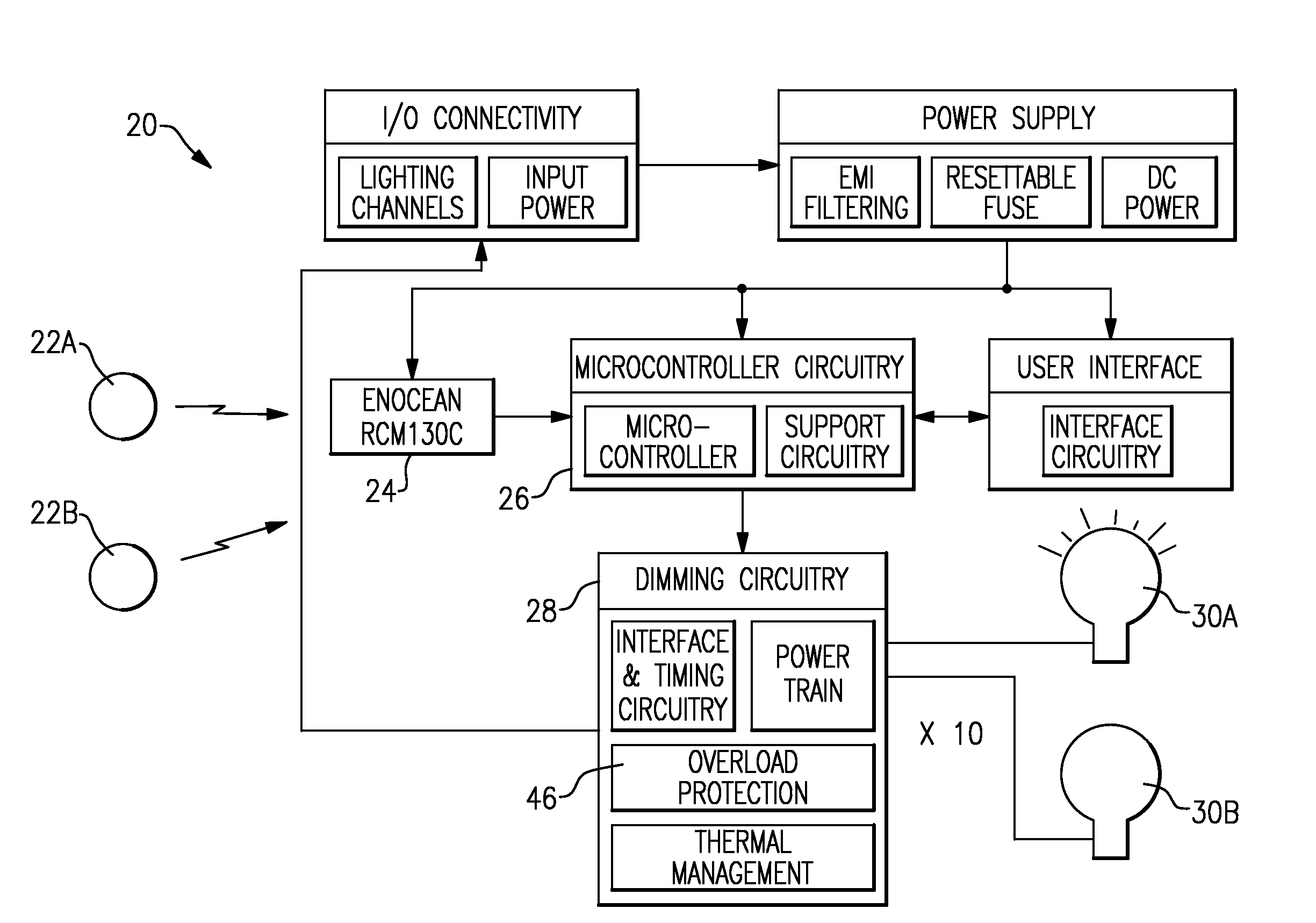
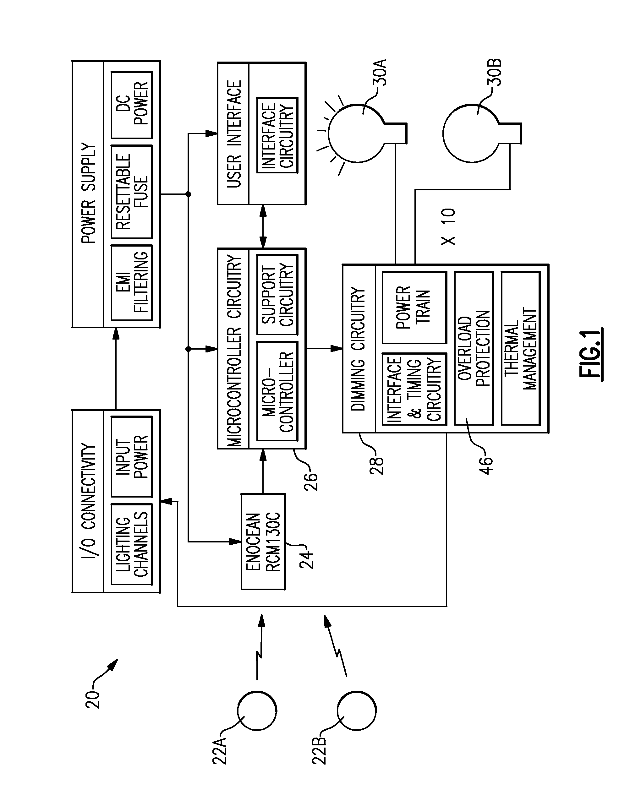
[0012]FIG. 1 shows a lighting control circuit 20 for a building. As shown, a plurality of dimmer switches 22A, 22B, etc. communicate through a wireless connection to a multi-channel receiver and controller 24. This receiver may be as available from Enocean, and available for example under its Product No. RCM130C. The use of a wireless receiver and wireless switches are not limiting on this invention, but only mentioned as one possible type of system.

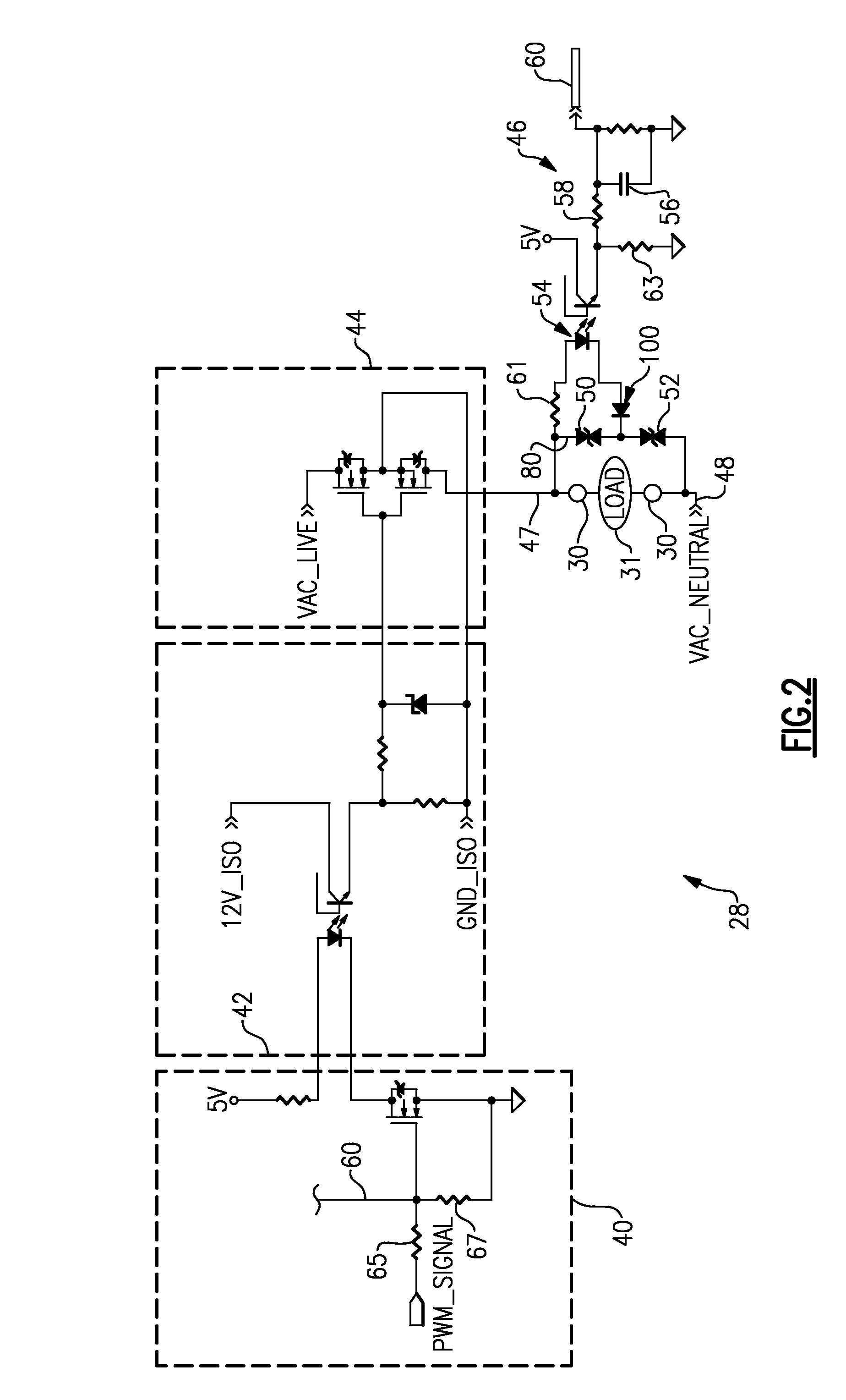
[0013]The receiver 24 communicates with a microcontroller 26, which in turn communicates with dimmer circuit 28. The dimmer circuit 28 controls the intensity of several lights 30A, 30B, etc. As shown within the dimmer circuit 28, there is a load protection 46. As mentioned above, one purpose of this load protection is to prevent damage to the load when an inductive load is connected to the circuit.

[0014]Dimmer circuit 28 is illustrated in FIG. 2. As shown, a microcontroller creates a pulse width modulated signal input at box 40. This sig...


PUM


Abstract

A lighting control circuit includes a dimmer circuit which is provided for an electrical outlet. An inductive load detection circuit is provided for identifying the presence of an inductive load in the electrical outlet. When an inductive load is sensed, dimming of the power directed to the electrical outlet is stopped such that full power is delivered to prevent damage to the load. The inductive load detection circuit identifies the presence of an induction load by sensing voltage spikes. In one embodiment, diodes which have a high impedance at lower voltages, but are largely conductive at higher voltages are utilized to achieve this control.

Description

BACKGROUND OF THE INVENTION[0001]This application relates to an inductive load sensor for sensing the presence of an inductive load and wherein the sensor looks for voltage spikes.[0002]Electrical systems for providing control of lighting are known. Switches are typically provided for actuating the lights between on and off positions. One known switch is a dimmer switch. A dimmer switch may be actuated to change the intensity of the light across an infinite number of levels. Thus, a user of the space being lighted can adjust the light to a desirable level.[0003]Dimmer switches are also associated with electrical outlets in some applications. As one example, builders will sometimes provide a dimmable electrical outlet as a way of providing dimmable light within a room. This is less expensive than providing a separate lighting circuit and switch. Thus, electrical outlets controlled by a dimmer switch are known.[0004]One problem with such electrical outlets is that there is no way to g...

Claims


Application Information

Patent Timeline
IPC IPC(8): H05B41/36
CPCY02B20/148H05B39/048Y02B20/00H05B39/04H02M5/293
Inventor XU, JIANIOTT, JEFFREY
Owner ENOCEAN
Why Eureka
Try Eureka