Light Scattering Type Smoke Detector
- Summary
- Abstract
- Description
- Claims
- Application Information
AI Technical Summary
Benefits of technology
Problems solved by technology
Method used
Image

Examples
first embodiment
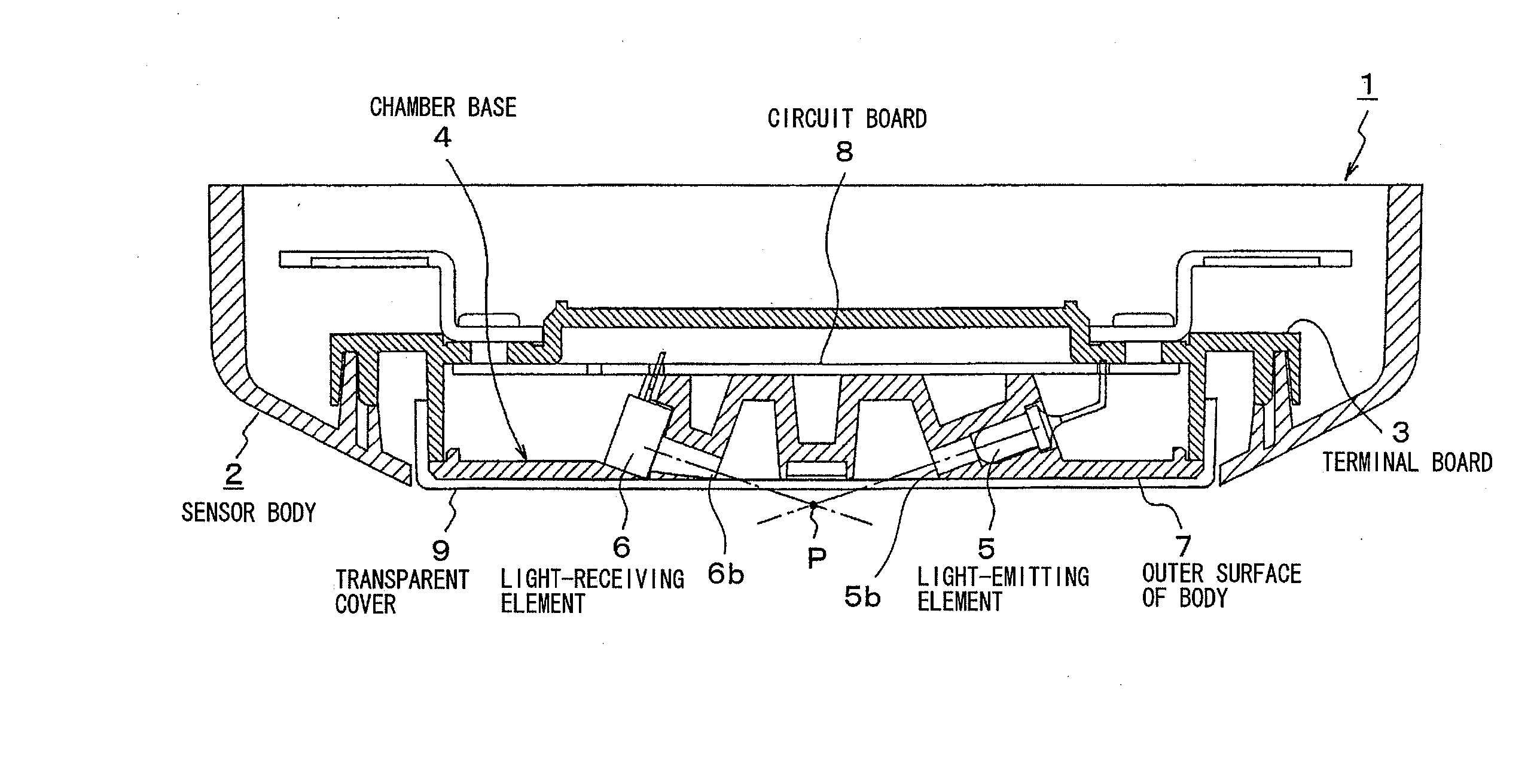
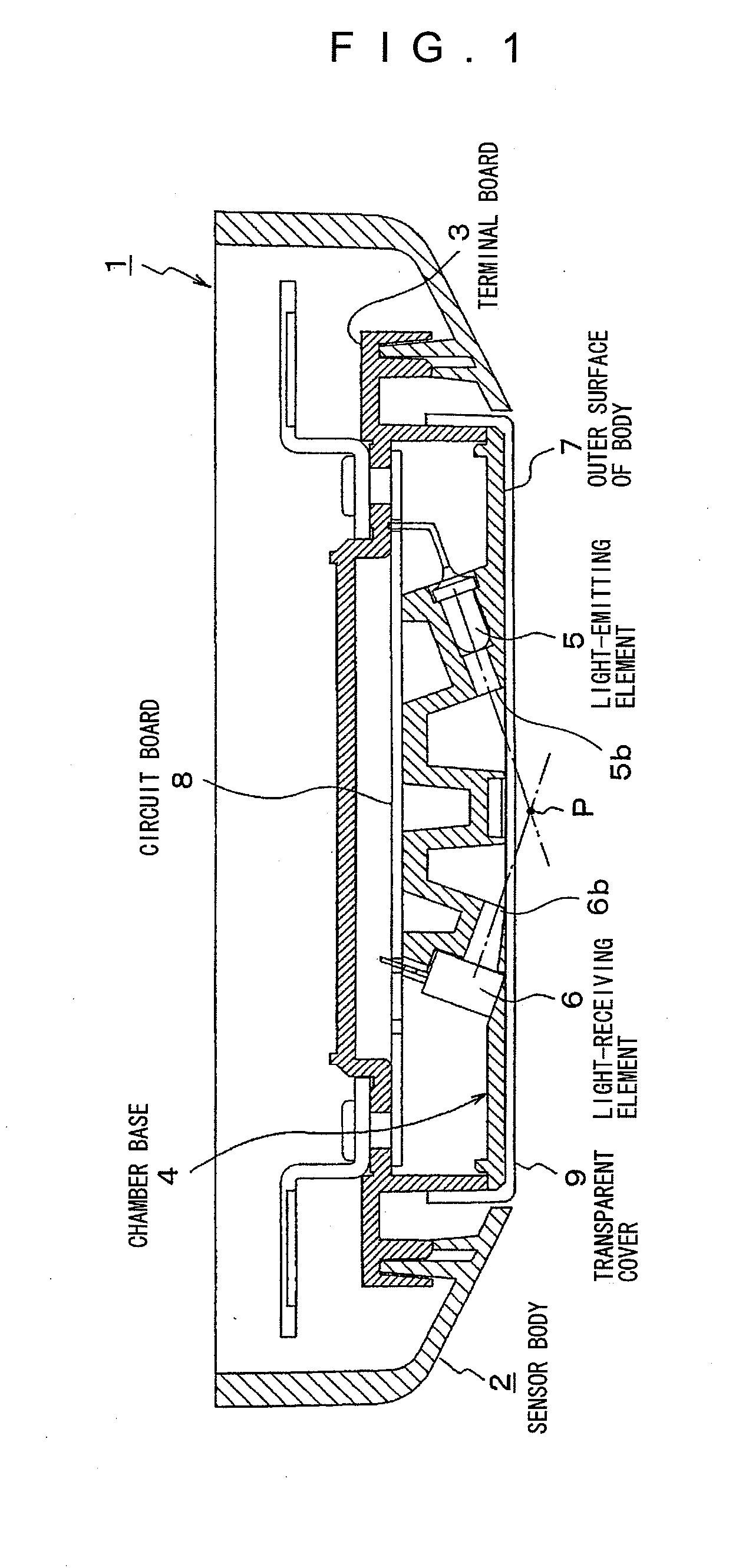
[0120] An outer surface 7 of the sensor body is a lower surface of the chamber base 4 and formed substantially flat, and the transparent cover 9 is attached to the outer surface 7 of the sensor body. Further, the outer surface 7 of the sensor body has a light-emitting opening 5b for ejecting the light emitted from the light-emitting element 5 to the outside of the smoke sensor 1 using scattering light, and a light-receiving opening 6b for introducing light thus ejected and scattered by smoke into the light-receiving element 6. In an outside open space further below the outer surface 7 of the sensor body, a light axis crossing point P is set, at which a light axis of the light-emitting element 5 and a light axis of the light-receiving element 6 mutually intersect with each other, and the light axis crossing point P constitutes a smoke-sensing point. Thus, one of characteristics of the smoke sensor 1 using scattering light is that the smoke-sensing point is set outside the smoke sens...
second embodiment
[0173]FIG. 12 is a perspective view of a chamber base 41 of a smoke sensor 40 using scattering light (partly shown) according to the On the chamber base 41, a light-emitting opening 42 and a light-receiving opening 43 are arranged so as to intersect with each other at a predetermined angle on the outer surface of the sensor body. The light-emitting element 5 not shown is housed inside the light-emitting opening 42, whereas the light-receiving element 6 not shown is housed inside the light-receiving opening 43.
[0174] Next, a relation between light emitting angle and light receiving angle will be described in detail. It should be noted that the present application incorporates Japanese Patent Application (JP-A) No. 2002-4221 filed on Jan. 11, 2002 by the present applicant, and a part of the description below is disclosed in the JP-A 2002-4221.
[0175]FIG. 13A schematically shows an optical positional relation corresponding to the positions at which the light-emitting unit and the ligh...
third embodiment
[0190] Hence, in the third embodiment, in addition to the elimination of the smoke chamber in the smoke sensor for realization of a thinner and smaller smoke sensor, one of the objects is improvement in accuracy of smoke distinction for realization of secure prevention of non-fire alarm.
[0191] Next, the light scattering type smoke sensor according to the third embodiment will be described. FIG. 16 is a sectional view of the light scattering type smoke sensor according to the third embodiment. The smoke sensor 100 using scattering light schematically includes a sensor body 112, a terminal board 113, a chamber base 114, a first light-emitting element 109, a second light-emitting element 110 (not shown in FIG. 16), a light-receiving element 111, and a transparent cover 116. If not specified otherwise, the sensor body 112, the terminal board 113, the chamber base 114, the first light-emitting element 109, the light-receiving element 111, and the transparent cover 116 can be configured s...
PUM
 Abstract
Description
Claims
Application Information