Miniature Piezoelectric Motor and Method of Driving Elements Using Same

a piezoelectric motor and miniature technology, applied in piezoelectric/electrostrictive/magnetostrictive devices, mountings, instruments, etc., can solve the problems of too large motor types to be feasible for small-sized applications, design of piezoelectric motors, and inability to meet the requirements of small-sized applications. , to achieve the effect of reducing the overall module size, reducing the required working voltage of the stator, and high power efficiency and driving for

Inactive Publication Date: 2008-10-09
DONG SHUXIANG
View PDF11 Cites 34 Cited by
  • Summary
  • Abstract
  • Description
  • Claims
  • Application Information

AI Technical Summary

Benefits of technology

[0012]One advantage of the present invention is that the proposed piezoelectric motor has a thin and ring-type configuration, and a lens or other element can be integrated into the center of piezoelectric motor to be driven directly as one part of the rotor. This design allows reducing the overall module size, especially in the thickness direction. Another advantage over the piezoelectric actuators based on the conventional inertial force method is that it has higher power efficiency and driving force due to the standing wave drive and threaded mechanism. A further advantage of the present invention is that when configured with a threaded drive mechanism, the motor is not as sensitive to vibrations as inertial force actuators are. A still further advantage of the present invention is that it is possible that piezoelectric element(s) in the stator can be made into thin type, therefore, the required working voltage for the stator can be very low. A yet further advantage of the present invention is that the piezoelectric motor can provide a driving mechanism for a lens or other element in an integrated structure having fewer components, and hence, a lower fabrication cost.
is that the proposed piezoelectric motor has a thin and ring-type configuration, and a lens or other element can be integrated into the center of piezoelectric motor to be driven directly as one part of the rotor. This design allows reducing the overall module size, especially in the thickness direction. Another advantage over the piezoelectric actuators based on the conventional inertial force method is that it has higher power efficiency and driving force due to the standing wave drive and threaded mechanism. A further advantage of the present invention is that when configured with a threaded drive mechanism, the motor is not as sensitive to vibrations as inertial force actuators are. A still further advantage of the present invention is that it is possible that piezoelectric element(s) in the stator can be made into thin type, therefore, the required working voltage for the stator can be very low. A yet further advantage of the present invention is that the piezoelectric motor can provide a driving mechanism for a lens or other element in an integrated structure having fewer components, and hence, a lower fabrication cost.

Problems solved by technology

However, the prior art piezoelectric motor designs suffer from many drawbacks that prevent such smaller-sized applications.
However, these types of motors are too large in size to be feasible for smaller size applications such as camera-phone modules.
This rod-type motor can be made very small in diameter, but is difficult to be made short in axial length.
Furthermore, it has a complex structure and requires a relatively higher operating voltage.
Although this type of actuator is simple in structure and does not need a large piezoelectric element for driving, it still requires a relatively long rod for producing longitudinal vibrations.
In addition, this type of actuator is inefficient, has a weak driving force, and suffers from vibration-sensitive problems.
Although it can be operated at a low working voltage, this type of actuator suffers significantly from problems caused by the difference in resonance frequencies in L1 and B2 modes.
Even a slight difference in resonance frequencies of the two modes will result in its failure to operate.
This motor is applied to driving a calendar in a wristwatch, but its configuration is apparently not suited for driving a lens or other element in a linear motion.

Method used


Image

  • Miniature Piezoelectric Motor and Method of Driving Elements Using Same
  • Miniature Piezoelectric Motor and Method of Driving Elements Using Same
  • Miniature Piezoelectric Motor and Method of Driving Elements Using Same

Examples


Embodiment Construction

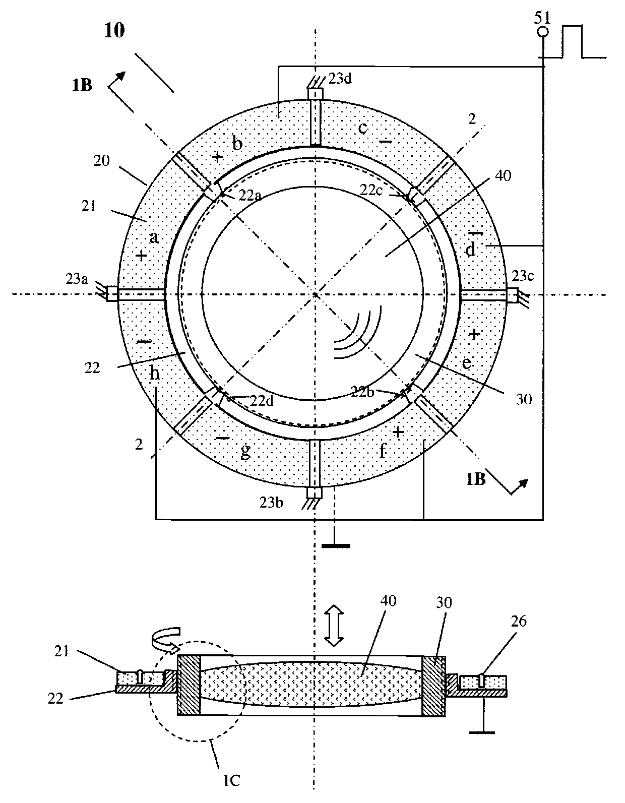
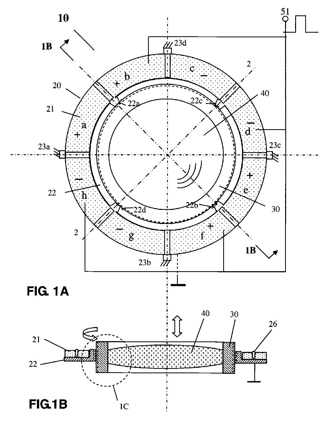
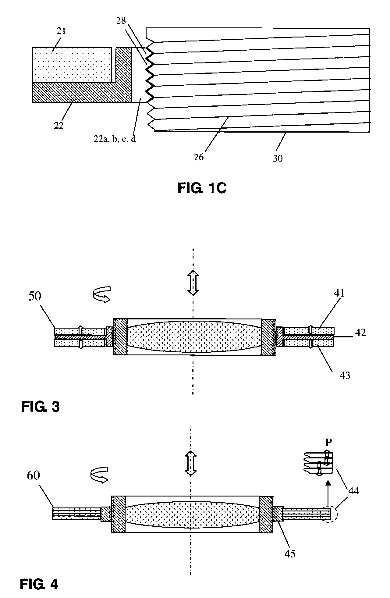
[0029]The present invention will now be described in detail with reference to the drawings, which are provided as illustrative examples of the invention so as to enable those skilled in the art to practice the invention. Notably, the figures and examples below are not meant to limit the scope of the present invention to a single embodiment, but other embodiments are possible by way of interchange of some or all of the described or illustrated elements. Moreover, where certain elements of the present invention can be partially or fully implemented using known components, only those portions of such known components that are necessary for an understanding of the present invention will be described, and detailed descriptions of other portions of such known components will be omitted so as not to obscure the invention. In the present specification, an embodiment showing a singular component should not be considered limiting; rather, the invention is intended to encompass other embodimen...


PUM


Abstract

The present invention provides a piezoelectric ultrasonic motors and a method of driving a motor with a standing wave. The motors include a thin ring / cylinder-type stator having one or two piezoelectric (ceramic or single crystal) rings / cylinders, coated with a segmented top / outer electrode and a bottom / inner electrode and poled in a thickness / radial direction, a metal ring / cylinder which is laminated with piezoelectric ring(s) / cylinder(s) having several inner threaded protrusions. The motor also includes a power source for supplying an alternating voltage to one group of electrodes of the piezoelectric stator to excite a standing wave vibration along one diameter direction of the stator ring / cylinder. The motor further includes a short cylinder rotor, which may have a lens inside for certain optical applications, or it may include other elements. The rotor is attached to the stator at the threaded surface of the protrusions and is driven to produce a circular motion, which may also be translated into a linear motion by the threaded surface through standing wave deformation at protrusions. Reverse motion of the rotor can be realized by applying the alternating voltage to another group of electrodes of the stator.

Description

CROSS-REFERENCE TO RELATED APPLICATIONS[0001]This application claims priority from U.S. Provisional Patent Application No. 60 / 921,814, filed Apr. 3, 2007, the contents of which are incorporated herein by reference in its entirety.FIELD OF THE INVENTION[0002]The present invention relates generally to piezoelectric motors. More particularly, the invention relates to a miniature piezoelectric motor that can drive its rotor and elements coupled thereto in a desired motion, and to a method of configuring and / or controlling such a motor to drive elements such as a lens or group of lenses more precisely and linearly.BACKGROUND OF THE INVENTION[0003]Piezoelectric micromotors have many features superior to conventional electromagnetic motors of comparable size, such as relatively higher power density, larger driving force, higher efficiency, faster responses, frictional lock in the power-off condition, and fewer parts in construction. More particularly, piezeolectric motors are capable of pr...

Claims


Application Information

Patent Timeline
Patent Type & Authority Applications(United States)
IPC IPC(8): G02B7/04H02N2/12
CPCG02B7/102H02N2/001H02N2/0095H02N2/103
Inventor DONG, SHUXIANG
Owner DONG SHUXIANG
Why Eureka
Try Eureka