Electrical circuit assembly for high-power electronics

a high-power electronics and circuit technology, applied in the direction of insulated conductors, cables, power cables, etc., can solve the problems of increasing the manufacturing cost of modules, generating a large amount of heat, and not only physically large components,

Inactive Publication Date: 2008-10-09
DEERE & CO
View PDF19 Cites 23 Cited by
  • Summary
  • Abstract
  • Description
  • Claims
  • Application Information

AI Technical Summary

Benefits of technology

[0010]In another form of the invention, an electronic control module includes a housing; a control board within the housing; and an electrical circuit assembly mounted to the housing. The electrical circuit assembly includes a electrical circuit substrate connected with the control board. The electrical circuit substrate includes a first side; a heat sink including a metal base plate having a first side and a second side, and a plurality of fins extending from the second side; and a thermally conductive and electrically insulating adhesive directly interconnecting at least a portion of the first side of the electrical circuit substrate with the first side of the base plate.

Problems solved by technology

These components are not only physically large, but also generate a high amount of heat, and are often sold and mounted as through-hole devices (devices which must be mounted through holes in the circuit board and may need to be hand-soldered in place.)
Through-hole devices cannot be easily mounted by automated methods such as pick-and-place machines, and require manual placement, which increases the manufacturing expense of the module.
Even in applications where through-hole devices are replaced with easier to place surface mount devices, the assembly of the power devices, heat sink, bus capacitors, bus structure, external power connectors, signal interconnect, and enclosure requires a great deal of labor and multiple processes.
A disadvantage of IMST is that the circuit and dielectric layers are bonded to a thin metal plate during the manufacturing process.
While this helps with the heat dissipation properties, it adds a costly manufacturing process.
Another disadvantage of an IMST approach is that the thermal resistance of the interface between the thin metal plate and the attached finned heat sink is high, which decreases the thermal efficiency.
A disadvantage of this type of arrangement is that a thin dielectric layer sandwiched between the circuit layer and the metal base layer must be baked (heat cured) in an oven, which requires an additional manufacturing step.

Method used


Image

  • Electrical circuit assembly for high-power electronics
  • Electrical circuit assembly for high-power electronics
  • Electrical circuit assembly for high-power electronics

Examples


Embodiment Construction

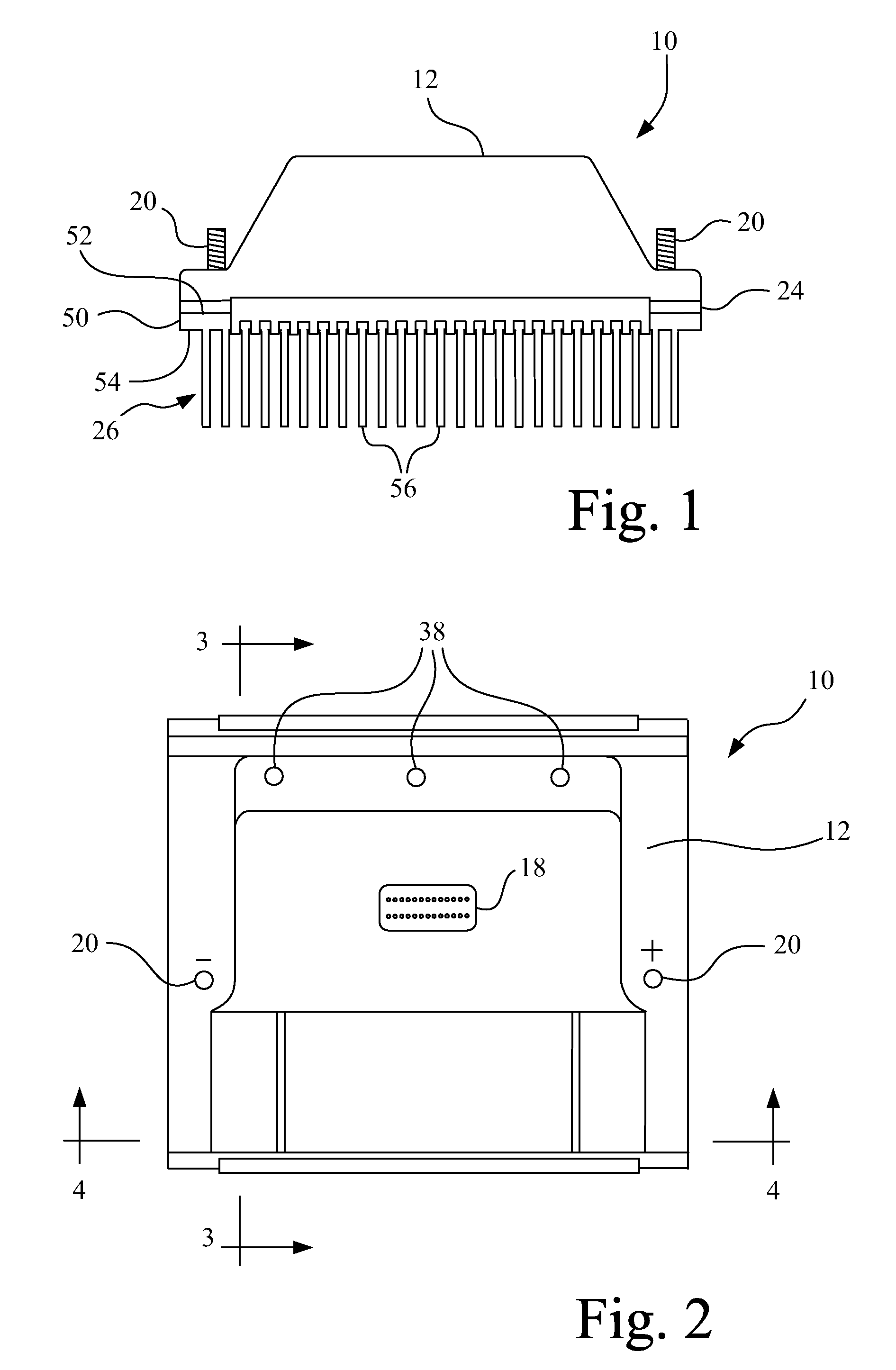
[0020]Referring now to the drawings, and more particularly to FIGS. 1-4, there is shown an embodiment of an electronic control module (ECM) 10 of the present invention. ECM 10 is used for high-current electric drive applications, such as a reel motor on a cutting platform of an agricultural combine or a traction motor for a work machine.

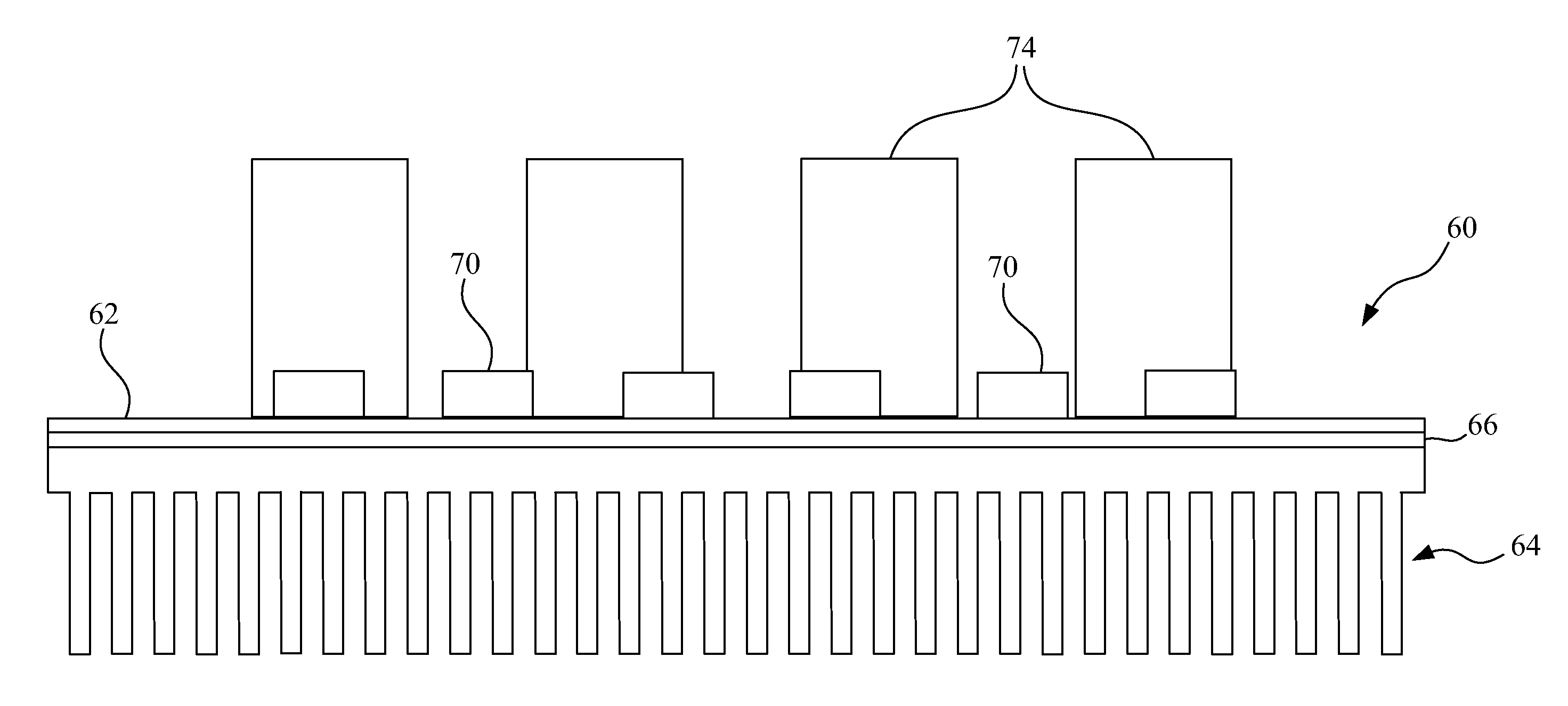
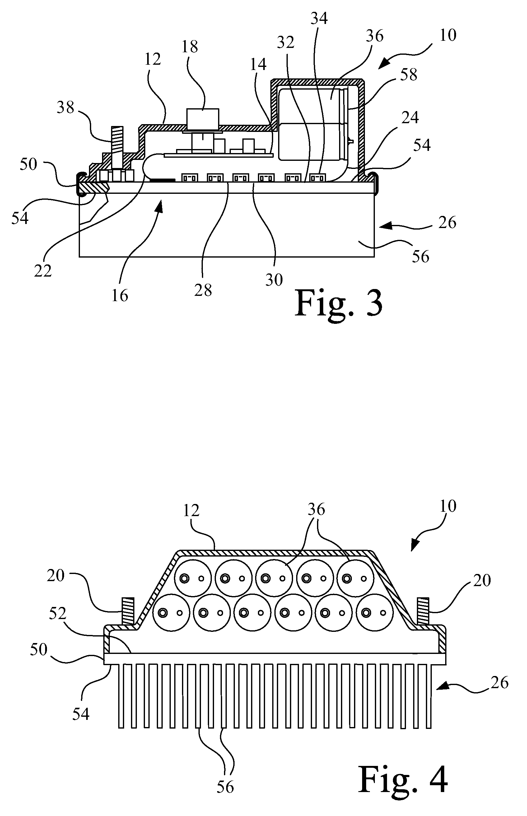
[0021]ECM 10 generally includes a housing 12, a control board 14 and an electrical circuit assembly 16. Housing 12 may be of any suitable configuration, and may be formed from any suitable material such as plastic or metal. Housing 12 carries control board 14, and provides external access to an input / output (I / O) connector 18 which is electrically connected with control board 14. Housing 12 also carries and provides access to a pair of input power terminals 20 which are electrically coupled with electrical circuit assembly 16. A flexible jumper circuit 22 interconnects control board 14 with electrical circuit assembly 16. Alternatively, control board...


PUM

PropertyMeasurementUnit
diameteraaaaaaaaaa
diameteraaaaaaaaaa
thickaaaaaaaaaa

Abstract

An electrical circuit assembly includes an electrical circuit substrate having a first side; a heat sink including a metal base plate having a first side and a second side, and a plurality of fins extending from the second side; and a thermally conductive and electrically insulating adhesive directly interconnecting at least a portion of the first side of the electrical circuit substrate with the first side of the base plate.

Description

CROSS REFERENCES TO RELATED APPLICATIONS[0001]This application is a continuation-in-part of U.S. application Ser. No. 11 / 545,633, entitled “Electrical circuit assembly for high-power electronics”, filed Oct. 10, 2006.FIELD OF THE INVENTION[0002]The present invention relates to electrical circuit assemblies, and, more particularly, to electrical circuit assemblies carrying high-power electronic components.BACKGROUND OF THE INVENTION[0003]Traditionally, high-current electronic applications such as electric motor drive controllers require the use of large electronic components to handle the current. These components are not only physically large, but also generate a high amount of heat, and are often sold and mounted as through-hole devices (devices which must be mounted through holes in the circuit board and may need to be hand-soldered in place.) Through-hole devices cannot be easily mounted by automated methods such as pick-and-place machines, and require manual placement, which inc...

Claims


Application Information

Patent Timeline
Patent Type & Authority Applications(United States)
IPC IPC(8): H05K3/00H05K7/20
CPCH05K1/0203H05K1/0206H05K1/0393H05K1/189H05K3/0061H05K3/3452Y10T29/49124H05K7/209H05K2201/0209H05K2201/09909H05K2201/10166H05K2201/10189H05K3/386
Inventor STAHLHUT, RONNIE D.GODBOLD, CLEMENT VANDENHOPMAN, JEFFREY GERALDKARNA, KARTHEEKSPRINGER, JAMES ARTHURALVES, JOHN LOPESALVES, LISE
Owner DEERE & CO
Why Eureka
Try Eureka