Resonant converter system and controlling method thereof having relatively better efficiency

a technology of resonant converter and control method, which is applied in the direction of electric variable regulation, process and machine control, instruments, etc., can solve the problems of increasing the loss of the circuit, the loss of the total converter is larger, and the resonant converter still has some problems, so as to achieve the effect of reducing the loss, reducing the loss, and improving the efficiency of the resonant converter

Active Publication Date: 2008-10-09
DELTA ELECTRONICS INC
View PDF8 Cites 101 Cited by
  • Summary
  • Abstract
  • Description
  • Claims
  • Application Information

AI Technical Summary

Benefits of technology

[0006]It is therefore an object of the present invention to provide a resonant converter system having a relatively better efficiency to adjust a phase angle and a frequency of the resonant converter system such that the resonant converter system would reach a relatively lower voltage gain and have a relatively lower loss when the resonant converter system is working under an abnormal status.

Problems solved by technology

However, the resonant converters still have some problems when simply adopting PFM during the abnormal status such as a circuit starting status or an output current-limiting status etc.
To achieve these requirements, the working frequency of the resonant converter has to be increased, and the increased working frequency means that the loss of the circuit is also increased.
The total loss of the converter is larger than the converter could bear when the frequency increased to a specific value, and the converter is thus damaged.
The aforementioned control method of simply changing the frequency can not solve the problem that the loss of the circuit is too big to bear when it is working under an abnormal status.
But through minishing the pulse-width, it may cause the hard-switching of the circuit which increases the total loss of the converter.

Method used


Image

  • Resonant converter system and controlling method thereof having relatively better efficiency
  • Resonant converter system and controlling method thereof having relatively better efficiency
  • Resonant converter system and controlling method thereof having relatively better efficiency

Examples


Embodiment Construction

[0037]An LLC resonant DC / DC converter and another resonant DC / AC converter among various resonant converters are employed as examples to describe the proposed method of the present invention.

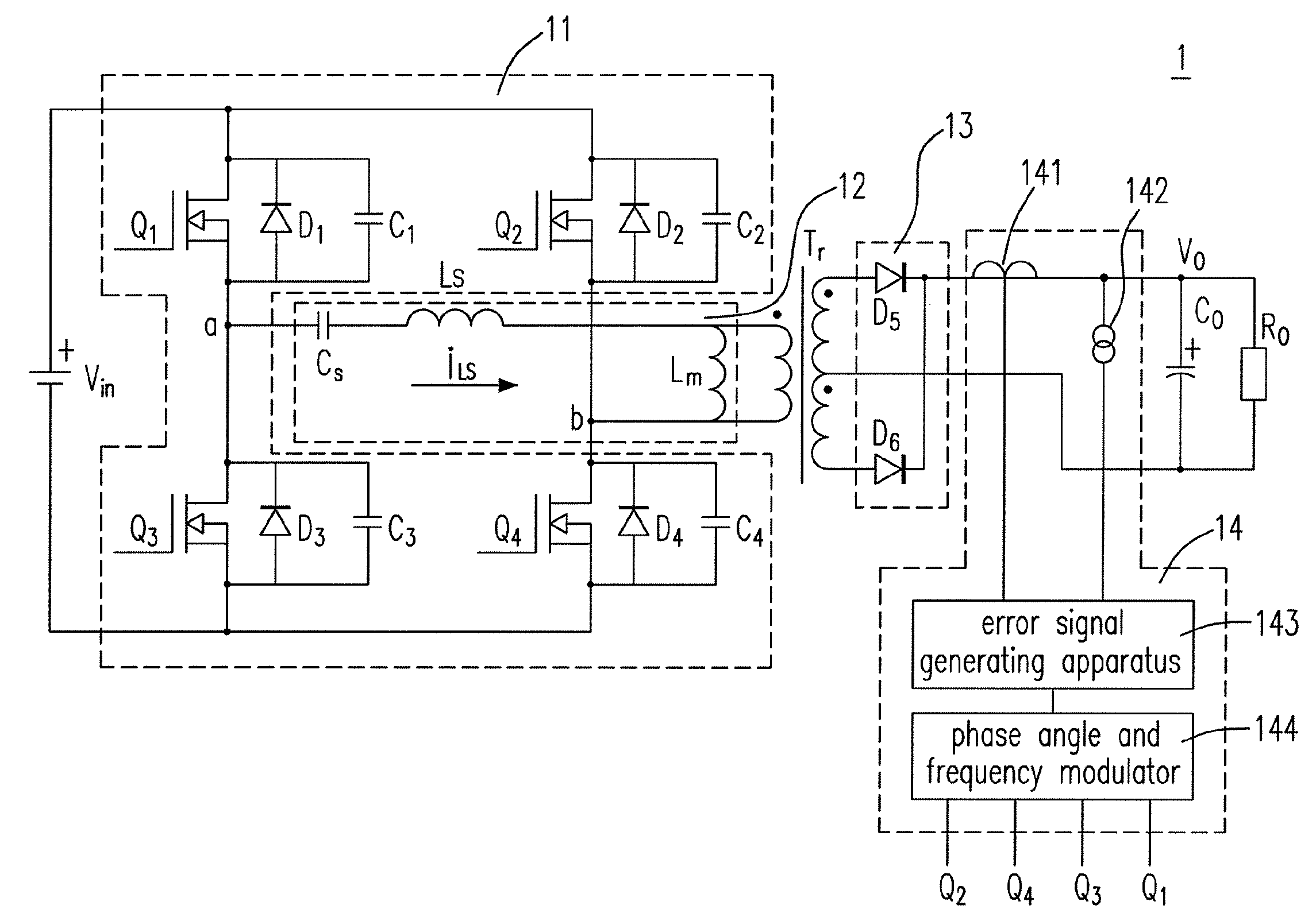
[0038]Please refer to FIG. 4(a), which shows a schematic circuit diagram of a LLC resonant DC / DC converter having a hybrid control apparatus according to the first preferred embodiment of the present invention. The LLC resonant DC / DC converter 1 includes a full-bridge DC / AC switching device 11, a resonant tank 12, a transformer Tr, a rectifier 13, a hybrid control apparatus 14, an output capacitor Co and a load Ro for receiving a DC input voltage Vin and generating a DC output voltage Vo. The full-bridge DC / AC switching device 11 includes a first switch Q1 electrically connected to a first diode D1 and a first capacitor C1 in parallel, a second switch Q2 electrically connected to a second diode D2 and a second capacitor C2 in parallel, a third switch Q3 electrically connected to a third diode D3...


PUM


Abstract

The configurations of a resonant converter system and a controlling method thereof are provided. The proposed resonant converter system includes a resonant converter and a hybrid control apparatus coupled to the resonant converter for generating a driving signal to adjust a phase angle and a frequency of the resonant converter such that the resonant converter would reach a relatively lower voltage gain and have a relatively lower loss during an abnormal operation.

Description

FIELD OF THE INVENTION[0001]The present invention relates to a resonant converter system. More particularly, the present invention relates to a resonant converter system having a hybrid control apparatus.BACKGROUND OF THE INVENTION[0002]The developing trend of the DC / DC converters is in the same direction like most of the power supply products that is to have the high efficiency, the high power density, the high reliability and the low cost. Since the resonant converters usually employ the controlling method of pulse frequency modulation (PFM), the zero-voltage switching of their switches is relatively easy to accomplish so as to achieve the requirements of high efficiency and high power density.[0003]However, the resonant converters still have some problems when simply adopting PFM during the abnormal status such as a circuit starting status or an output current-limiting status etc. A relatively lower voltage gain of the circuit is required when a resonant converter is working unde...

Claims


Application Information

Patent Timeline
Patent Type & Authority Applications(United States)
IPC IPC(8): H02M3/335
CPCH02M3/3376Y02B70/1433H02M2001/0058Y02B70/1491H02M1/0058Y02B70/10
Inventor YING, JIANPINGYE, YIQINGYAN, CHAOZENG, JIANHONG
Owner DELTA ELECTRONICS INC
Why Eureka
Try Eureka