

Dual flow fan heat sink application
Inactive Publication Date: 2008-10-09
DELPHI TECH INC
View PDF10 Cites 10 Cited by
- Summary
- Abstract
- Description
- Claims
- Application Information
AI Technical Summary
Benefits of technology
[0010]Accordingly, the subject invention increases cooling capabilities by allowing for communication between the air in the primary path and the hub. Air moves through the air passage in the hub to cool the motor assembly. In addition, air is moved over a heat sink core to create turbulence and further cool the heat sink assembly.
Problems solved by technology
This high temperature can greatly increase the wear of motor bearings and significantly reduce motor life.
Method used
View moreImage
Smart ImageViewing Examples

Examples
second embodiment
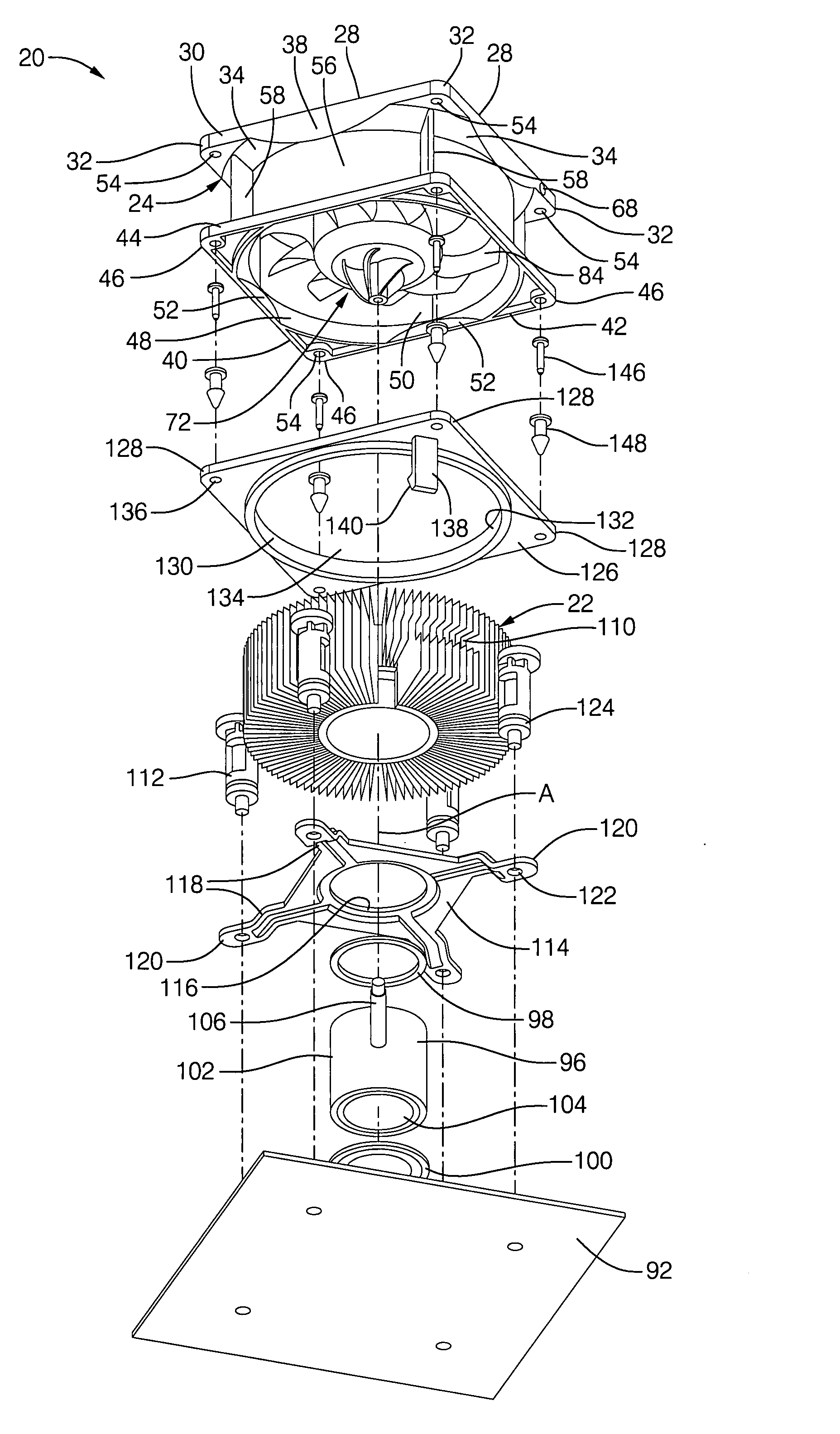
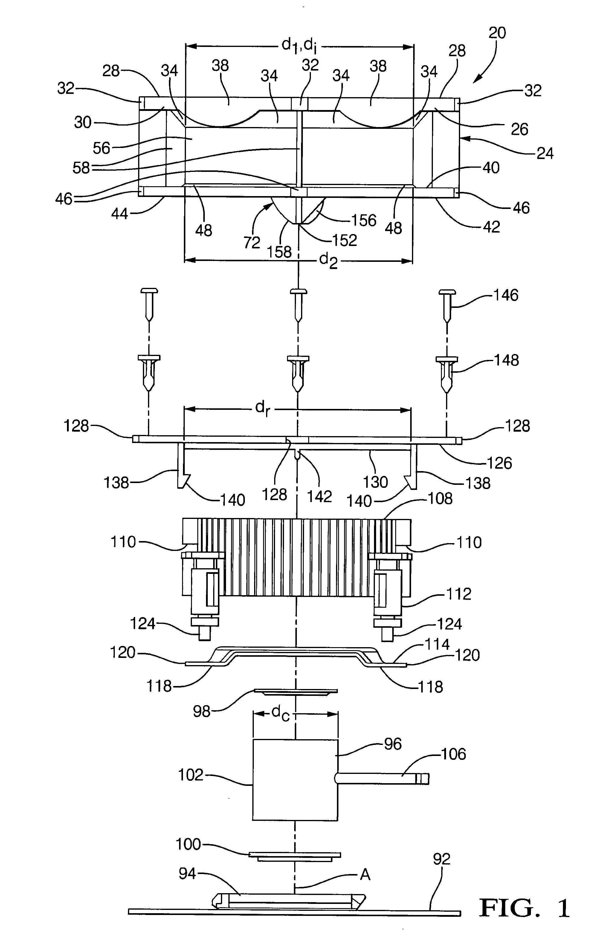
[0038]In the subject invention, each of the air vanes 156 extend axially from the hub bottom 76 a shorter distance adjacent the tube 152 than adjacent the gap 134. The air vanes 156 move the air over the top core portion 98 and through the air passage 154 to establish communication between the channels 90 and the air cavity 150.
third embodiment
[0039]In the subject invention, a shaft 160 that is hollow extends along the axis A and through the motor assembly 64 to the tube 152 to move air therethrough and to establish communication between the shaft 160 and the air cavity 150.
Login to View More PUM
 Abstract
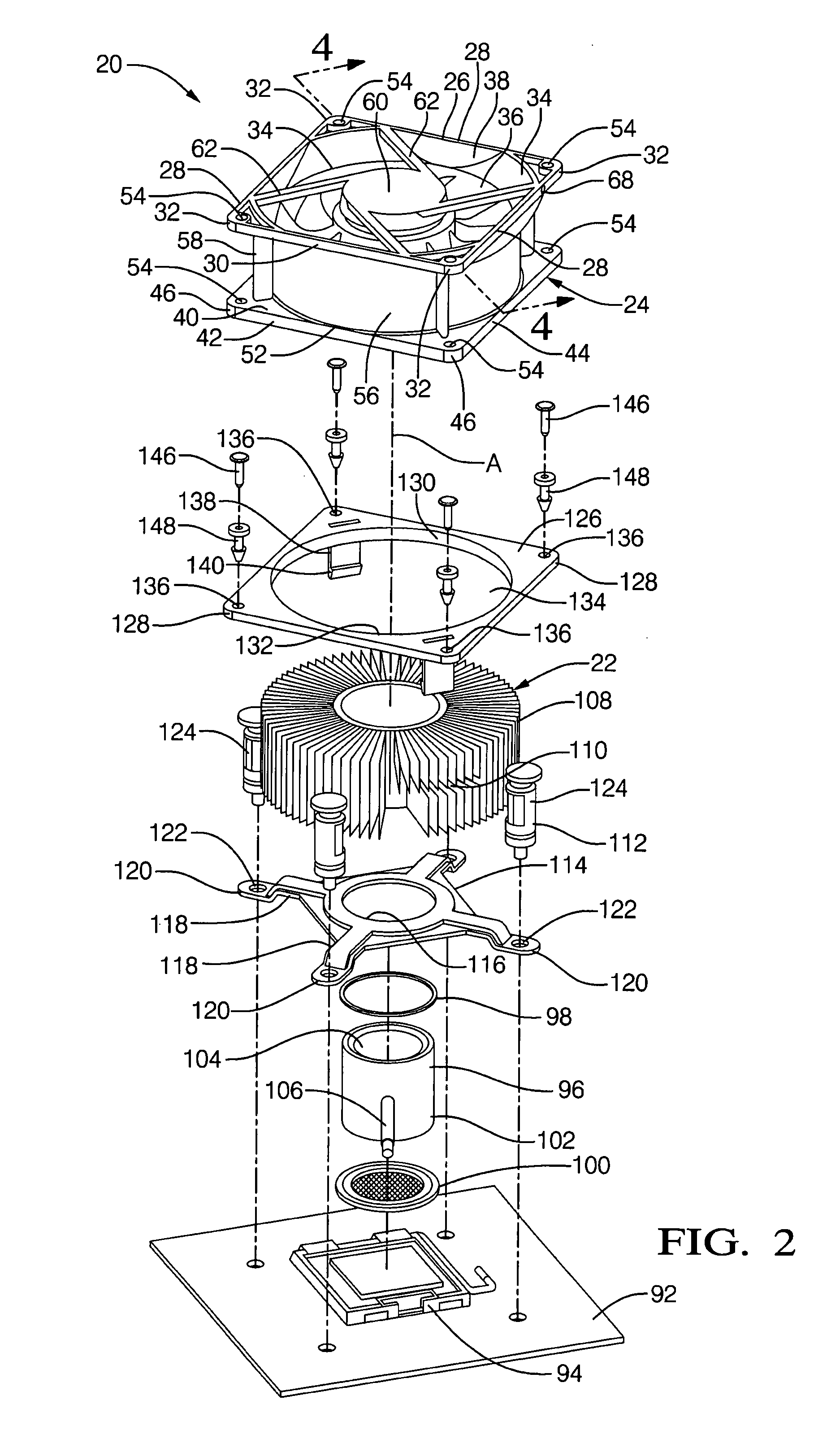
A cooling system includes a fan assembly that is rotated to move air in a primary path through a housing. The fan assembly includes a hub and a plurality of spaced reinforcing ribs that establish channels between a motor casing and the interior of the hub. A heat sink assembly is axially spaced from a hub bottom to define an air cavity that is in communication with a gap. The hub includes a tube that defines an air passage to establish communication with the cavity. A plurality of air vanes extend in a spiral path from the hub bottom and into the air cavity to move air through the air passage and create turbulence over the heat sink assembly. The air vanes move the air over the heat sink assembly and through the air passage to establish communication between the channels and the air cavity.
Description
BACKGROUND OF THE INVENTION[0001]1. Field of the Invention[0002]The subject invention relates to a cooling system for producing an airflow across a heat sink assembly and for cooling a blower motor.[0003]2. Description of the Prior Art[0004]Cooling systems having a fan assembly are typically rotated by motors. These motors generate their own internal heat during the normal course of operation. The internally generated heat is primarily due to Joule heating caused by electric current passing through the motors rotor and stator. This high temperature can greatly increase the wear of motor bearings and significantly reduce motor life.[0005]It is known in the art for cooling systems to have a housing that is disposed about an axis and a motor assembly that is rotatably supported by the housing on the axis. The previous cooling systems include a fan assembly that is rotatably secured to the motor assembly and extends radially from the axis. The fan assembly includes a hub and a plurality...
Claims
Login to View More Application Information
Patent Timeline
 IPC IPC(8): F04D29/58
CPCF04D29/584F04D29/646F04D25/0613F04D25/082F04D29/329F04D29/5806
InventorACRE, JAMES A.REYZIN, ILYAVETTER, STEPHAN MICHAEL
OwnerDELPHI TECH INC