Automatic transmission

a transmission and automatic technology, applied in mechanical equipment, transportation and packaging, gearing, etc., can solve the problems of weak feeling or indication of speed change, driver cannot obtain a sufficient feeling of acceleration, and the rotation frequency drop within the range of effective rotation of the engine becomes sligh

Inactive Publication Date: 2008-10-09
AISIN AW CO LTD
View PDF7 Cites 21 Cited by
  • Summary
  • Abstract
  • Description
  • Claims
  • Application Information

AI Technical Summary

Benefits of technology

[0008]According to a non-limiting embodiment of the, the step ratios that are the increasing ratios of gear ratios (the rotational frequency of an input shaft / the rotational frequency of an output shaft) when the shift stage is raised up by one stage is distributed without any large deviation at every shift stage. Further, the values of step ratios at respective shift stage become values that are separated from “1”, i.e., values larger than 1.1 at which it is possible to expect to provide an indication of speed change. Accordingly, by properly distributing the step ratios between the respective shift stages, a sufficient feeling of acceleration can be obtained as a clear indication of speed change at the time of speed change accompanied by acceleration.
[0009]In a further non-limiting embodiment, a third control clutch for preventing the high-speed rotation of the first sun gear and the second sun gear is provided.
[0010]According to a non-limiting embodiment, a situation in which the first sun gear and the second sun gear that are connected to each other is reversely rotated at very high speed can be avoided by disconnecting the third control clutch at the time of predetermined shift change.

Problems solved by technology

Further, if the values of the step ratios themselves at respective shift stages are excessively small ((that is, values near “1”), the drop of the rotational frequency within the range of effective rotation of an engine becomes slight, for example, at the time of speed change accompanied by acceleration.
Therefore, a feeling or indication of speed change becomes weak, and a driver cannot obtain a sufficient feeling of acceleration at the time of speed change.
Moreover, the step ratio between the sixth shift stage and a seventh shift stage that are high-speed stages becomes a small step ratio less than 1.1 at which it is not possible to expect to provide an indication of speed change.

Method used


Image

  • Automatic transmission
  • Automatic transmission
  • Automatic transmission

Examples


first embodiment

[0032]Hereinafter, a first non-limiting embodiment of an automatic transmission according to the invention will be explained referring to FIGS. 1 to 3.

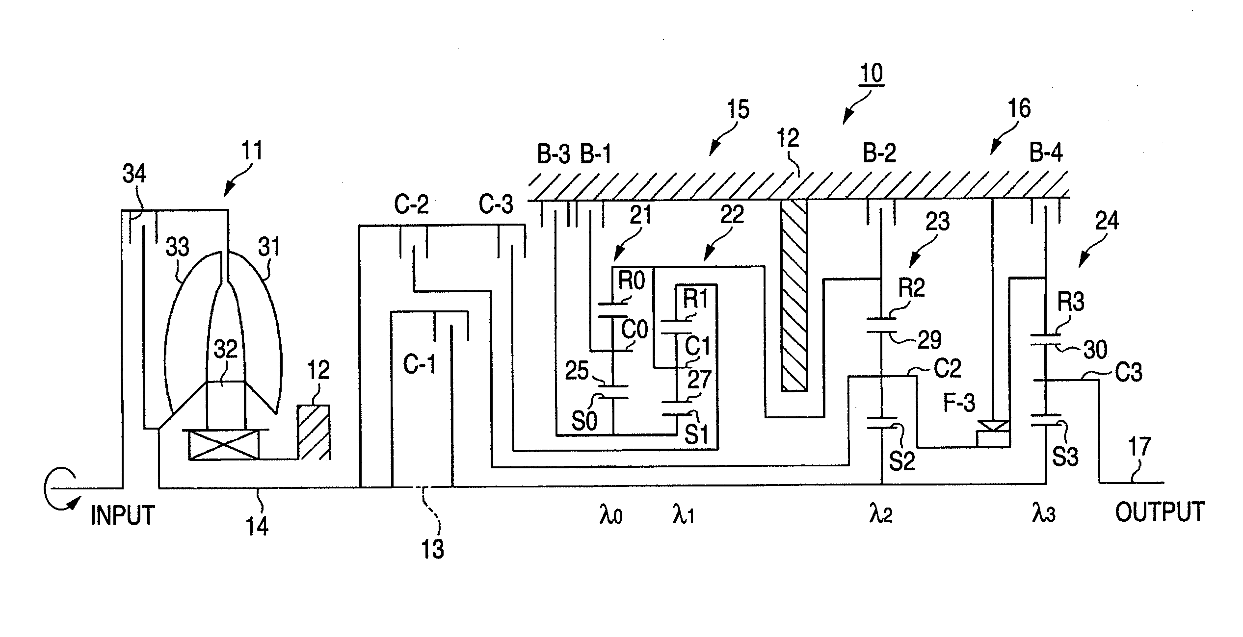
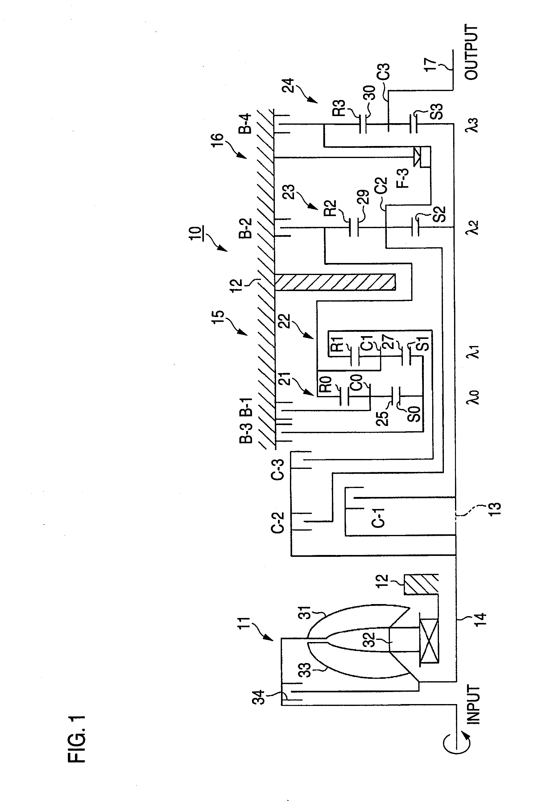
[0033]FIG. 1 shows a skeleton view of the automatic transmission 10 of this embodiment. The automatic transmission 10 is used in order to change and transmit the speed of the output rotation of the hydraulic torque converter 11, which is rotationally driven by, for example, an engine of an automobile, to driving wheels. As shown in FIG. 1, the automatic transmission 10 includes a transmission case 12 attached to a vehicle body, an input shaft 14, a dual planetary gear train 15 for speed reduction, and a dual planetary gear train 16 for speed change, and an output shaft 17, which are provided sequentially (from the left to the right in FIG. 1) from the front to the rear at a common axis 13 passing through almost the center in the transmission case 12.

[0034]As shown in FIG. 1, in the dual planetary gear train 15 for speed reduction, a s...

second embodiment

[0074]Next, a second non-limiting embodiment according to the automatic transmission of the invention will be explained referring to FIGS. 4 and 5. In addition, this second embodiment is different from the first embodiment in the arrangement place of the third control clutch, and is common to the first embodiment in other configurations. Accordingly, portions that are different from those of the first embodiment will be mainly explained below, and duplicate explanation of common members is omitted by giving the same reference numerals thereto.

[0075]Now, in the automatic transmission 10 of this embodiment, as shown in FIG. 4, in the dual planetary gear train 15 for speed reduction, the second ring gear R1 of the second planetary gear mechanism 22 is connected to the input shaft 14 so that the rotation of the input shaft 14 may be transmitted to the second ring gear R1. On the other hand, the second carrier C1 of the second planetary gear mechanism 22 in the dual planetary gear train ...

third embodiment

[0079]Next, a third non-limiting embodiment according to the automatic transmission of the invention will be explained referring to FIGS. 6 and 8. In addition, this third embodiment is different from the first embodiment in that it does not have the third control clutch, and is common to the first embodiment in other configurations. Accordingly, portions that are different from those of the first embodiment will be mainly explained below, and duplicate explanation of common members is omitted by giving the same reference numerals thereto.

[0080]Now, in the automatic transmission 10 of this embodiment, as shown in FIG. 6, in the dual planetary gear train 15 for speed reduction, the second ring gear R1 of the second planetary gear mechanism 22 is connected to the input shaft 14 so that the rotation of the input shaft 14 may be transmitted to the second ring gear R1. In addition, for the rest, as shown in FIG. 6, the respective members in the automatic transmission 10 are the same as th...


PUM


Abstract

An automatic transmission having a second ring gear of planetary gear mechanisms and is connected to an input shaft so as to be able to transmit power thereto, and a first sun gear and a second sun gear, and a first carrier that are connected to each other are in turn connected to a third control brake and a first control brake, respectively. A third sun gear and a fourth sun gear of the planetary gear mechanisms are connected to each other, and are in turn detachably connected to the input shaft 14 by a first control clutch. A third ring gear R2 and a fourth ring gear R3 are connected to a second control brake and a fourth control brake, respectively. Furthermore, a third carriers is detachably connected to the input shaft by a second control clutch, and a fourth carrier is connected to an output shaft.

Description

TECHNICAL FIELD[0001]Exemplary embodiments of the present invention relate to an automatic transmission that changes the speed of the rotation of an input shaft to a plurality of stages by a planetary gear train, to transmit it to an output shaft.BACKGROUND ART[0002]Conventionally, as this type of automatic transmission, for example, an automatic transmission described in Patent Document 1: Japanese Unexamined Patent Application Publication No. 2002-213545 (hereinafter referred to as “conventional automatic transmission”) is known. In this Patent Document 1, an automatic transmission that includes a dual planetary gear train for speed reduction in which a common sun gear directly connected to an input shaft meshes with a first ring gear via a small-diameter pinion with a stepped pinion provided by a carrier, and meshes with a second ring gear via a large-diameter pinion with a stepped pinion. A dual planetary gear train for speed change is provided in which a sun gear of a first sin...

Claims


Application Information

Patent Timeline
Patent Type & Authority Applications(United States)
IPC IPC(8): F16H3/62
CPCF16H3/66F16H2200/006F16H2200/0086F16H2200/2012F16H2200/2048F16H2200/2051
Inventor KATO, TAKAAKIFUKAYA, TSUYOSHIOGAWA, TAKASHIHONGOYA, AKIHITOTSUKAMOTO, HIROYUKI
Owner AISIN AW CO LTD
Why Eureka
Try Eureka