Shifting Apparatus and Shifting Control Method Thereof

a technology of shifting control and shifting apparatus, which is applied in the direction of mechanical apparatus, digital data processing details, instruments, etc., can solve the problems of prolonged period, suppress the sense of incongruity resulting from an unsuppressed amount of consumption, suppress the consumption of energy, and suppress the effect of fuel consumption

Inactive Publication Date: 2008-10-09
TOYOTA JIDOSHA KK
View PDF10 Cites 12 Cited by
  • Summary
  • Abstract
  • Description
  • Claims
  • Application Information

AI Technical Summary

Benefits of technology

[0026]According to the shifting apparatus and shifting control method thereof as described above, the remaining amount of energy supplied to the power unit is detected, and synchronization by the synchronization means is prohibited and synchronization by the synchronization mechanism is carried out if the remaining amount of energy thus detected is smaller than a predetermined remaining amount. Thus, when the remaining amount of energy is smaller than the predetermined remaining amount, consumption of a larger amount of energy can be prohibited from being caused by, for example, a rise in the output rotational speed of the power unit resulting from synchronization by the synchronization means. As a result, a deterioration in fuel consumption can be suppressed, and a sense of incongruity resulting from an unsuppressed amount of consumption can be suppressed, for example, in the case where the driver desires to suppress the consumption of energy.

Problems solved by technology

Hence, the shifting period is prolonged, and a sense of incongruity resulting from undesired performance of shifting may be conveyed to the driver of the vehicle.

Method used


Image

  • Shifting Apparatus and Shifting Control Method Thereof
  • Shifting Apparatus and Shifting Control Method Thereof
  • Shifting Apparatus and Shifting Control Method Thereof

Examples


Embodiment Construction

[0036]In the following description and the accompanying drawings, the invention will be described in more detail in terms of exemplary embodiments. In the following description, like components are denoted by like reference symbols. Those components which are accompanied by the same reference symbol are identical in name and function and therefore will not be repeatedly described in detail.

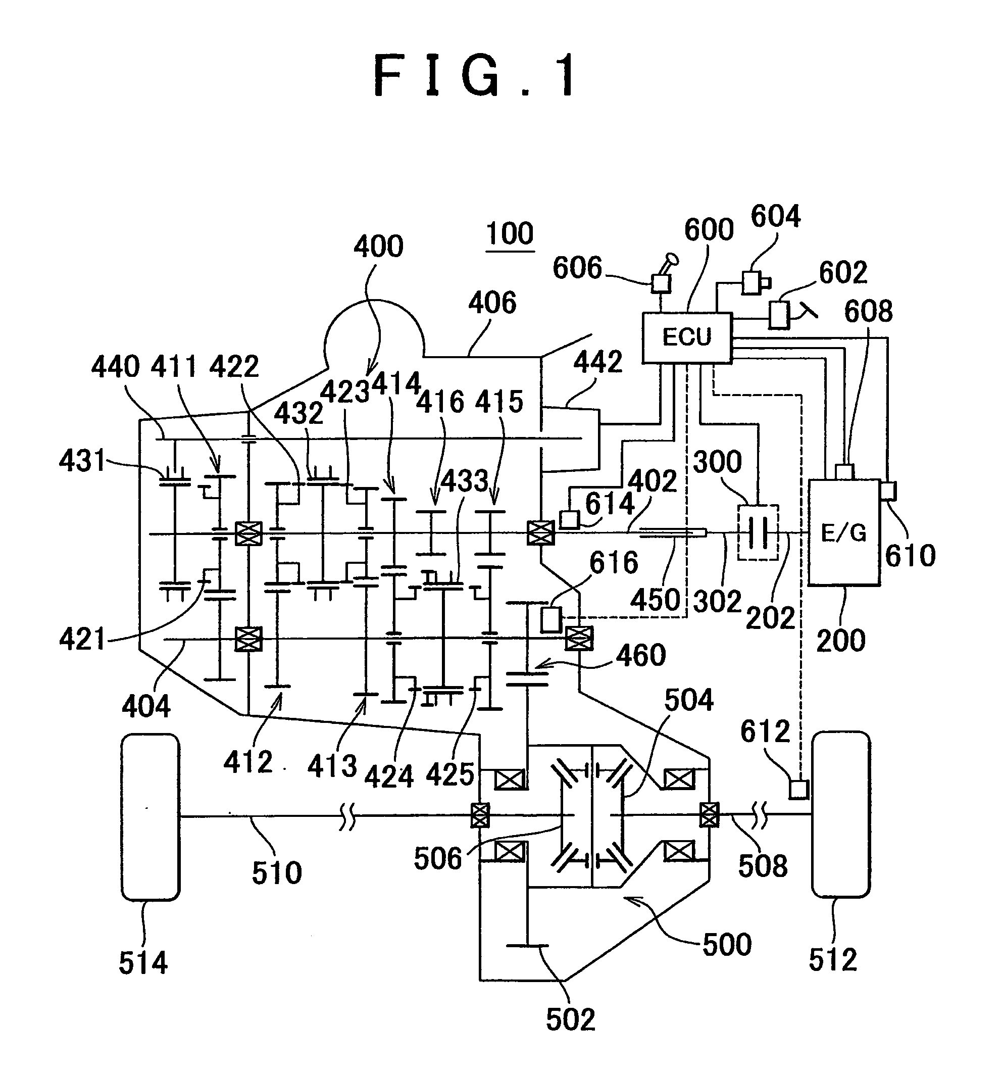
[0037]Referring to FIG. 1, a vehicle mounted with a shifting apparatus according to a first embodiment of the invention will be described. A vehicle 100 is an FF (front-engine front-drive) vehicle. It is not absolutely required that the vehicle mounted with the shifting apparatus according to the invention be an FF vehicle.

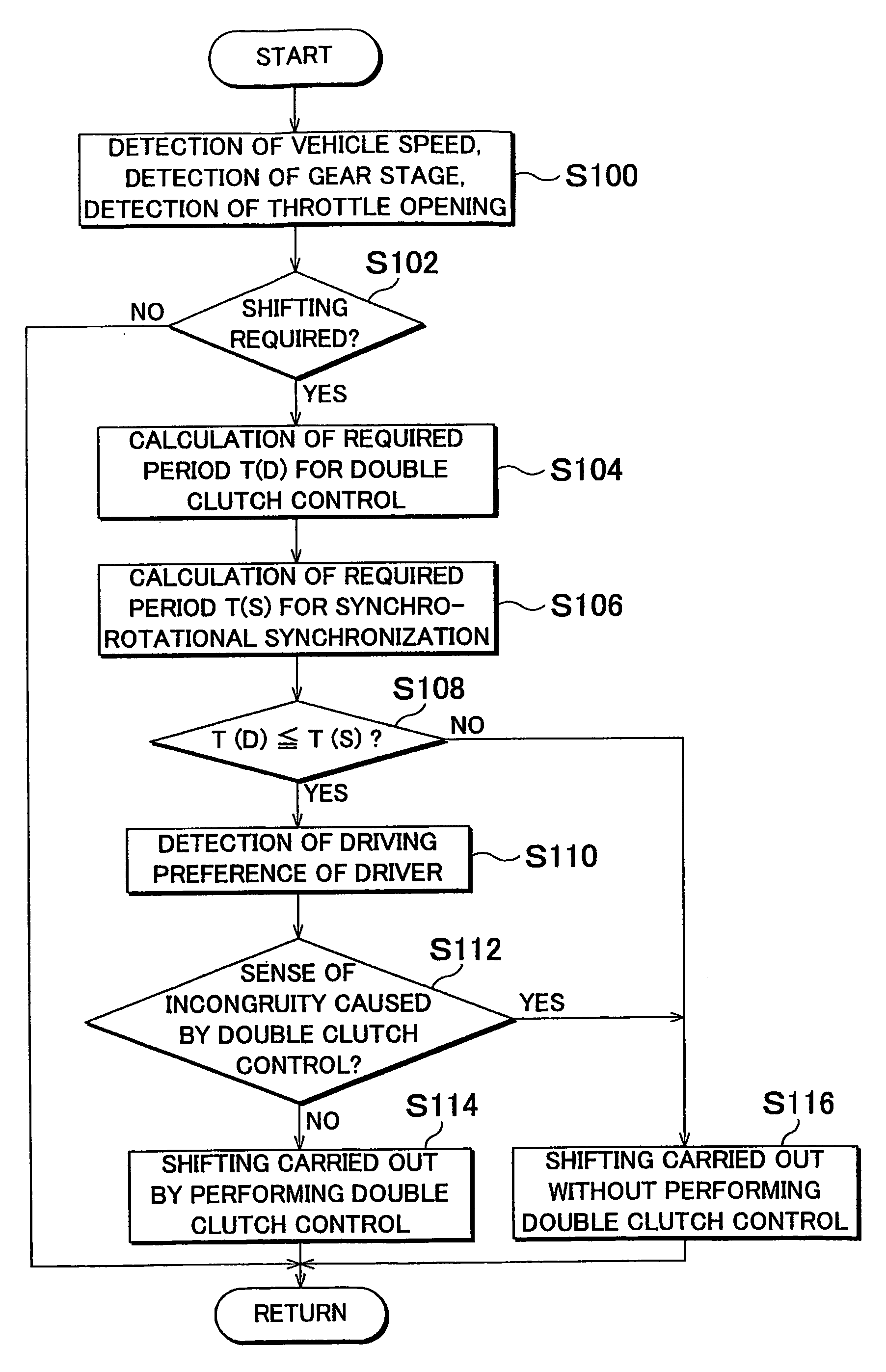
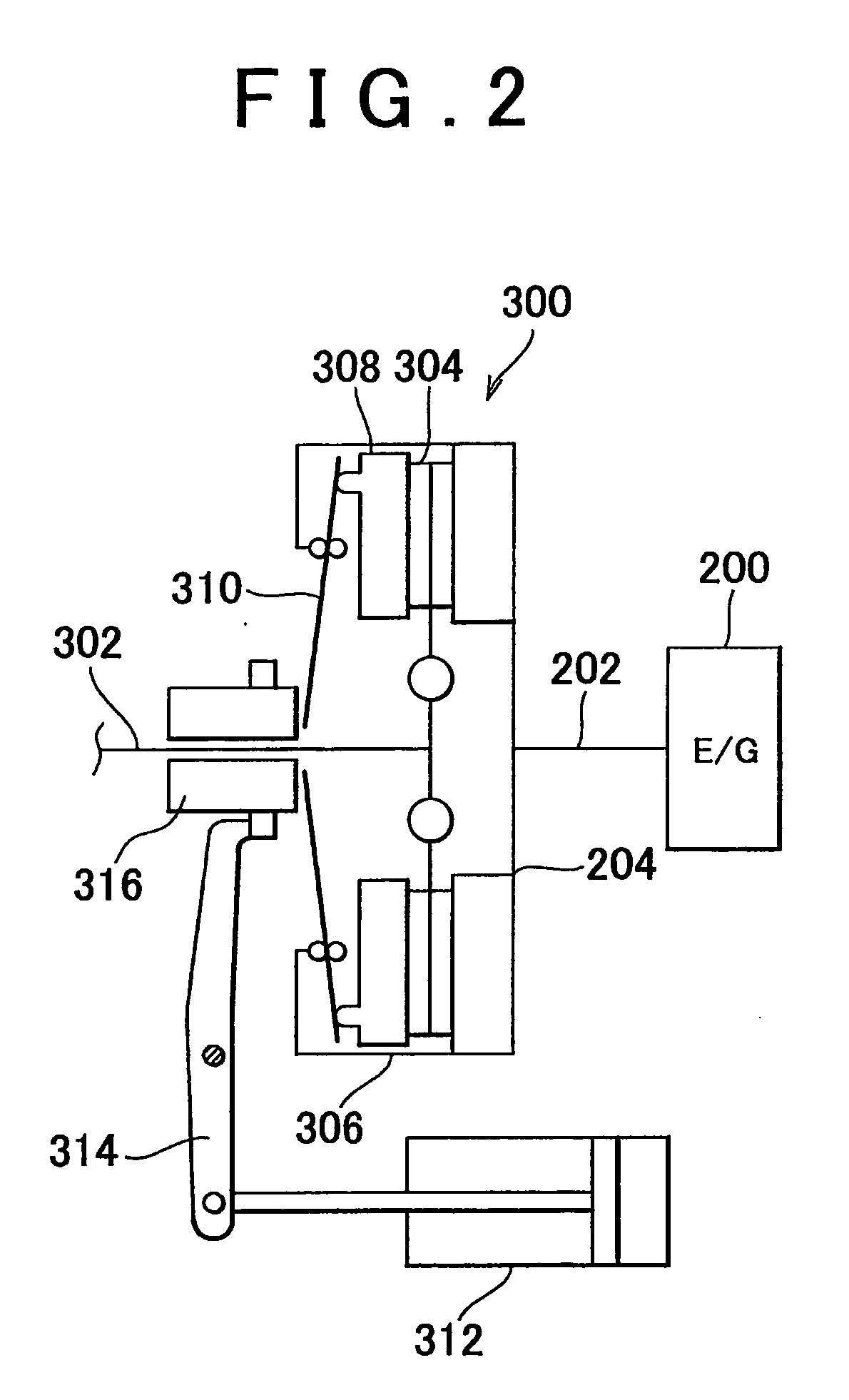
[0038]The vehicle 100 is a vehicle with no clutch pedal wherein a desired gear stage is established by operating, by means of an actuator, a clutch and a normally meshed gear transmission that is identical in type with a manual transmission of the related art. In the vehicle 100...


PUM


Abstract

An ECU executes a program including a step of detecting a running speed of a vehicle and a current gear stage of the vehicle, a step of determining whether or not shifting is required, a step of calculating a required period T(D) for performing double clutch control if shifting is required, a step of calculating a required period T(S) for synchro-rotational synchronization, a step of determining whether or not the required period T(D) for double clutch control is equal to or shorter than the required period T(S) for synchro-rotational synchronization, and a step of carrying out shifting by performing double clutch control if the required period T(D) for double clutch control is equal to or shorter than the required period T(S) for synchro-rotational synchronization. A sense of incongruity felt by a driver during shifting is thereby suppressed.

Description

BACKGROUND OF THE INVENTION[0001]1. Field of the Invention[0002]The invention relates to a shifting apparatus and a shifting control method thereof. In particular, the invention relates to a normally meshed gear transmission and a shifting control method thereof.[0003]2. Description of the Related Art[0004]There has been known a related art wherein an actuator is used to engage or release a clutch and select a gear stage in a shifting apparatus having a normally meshed gear transmission. In some of shifting apparatuses thus constructed, so-called double clutch control is performed. That is, in switching from one gear stage to another (e.g., in performing downshift), a clutch is temporarily engaged in a neutral state to cause a rise in engine speed, so that input and output shafts of a normally meshed gear transmission will synchronize with each other.[0005]Japanese Patent Application Laid-Open No. 2001-280472 discloses a rotational synchronization device for a transmission which sui...

Claims


Application Information

Patent Timeline
Patent Type & Authority Applications(United States)
IPC IPC(8): F16H61/04G06F17/00F16H59/44F16H61/28F16H59/70F16H61/682F16H61/688
CPCB60W2560/02F16H59/44F16H59/70F16H61/0403F16H61/688Y10T477/641F16H2302/04F16H2302/06F16H2059/003Y10T477/69335F16H2061/0015B60W2530/209
Inventor OTSUBO, MASAAKI
Owner TOYOTA JIDOSHA KK
Why Eureka
Try Eureka