Implant Back-Injecting Device

Inactive Publication Date: 2008-10-09
IPSEN PHARMA SAS
View PDF10 Cites 17 Cited by
  • Summary
  • Abstract
  • Description
  • Claims
  • Application Information

AI Technical Summary

Benefits of technology

[0021]This second variant is preferred to the first in that it avoids tolerance pro

Problems solved by technology

In course of use, it has been observed that the use of a back injection device of the type described above is not always convenient and is often misunderstood by practitioners.
However, these practitioners hold the main body firmly in their other hand, which makes it impossible for the main body to return to its proximal position and thus

Method used


Image

  • Implant Back-Injecting Device
  • Implant Back-Injecting Device
  • Implant Back-Injecting Device

Examples


Embodiment Construction

[0085]Hereafter, the “proximal” end means the end located on the side of the practitioner, and the “distal” end means the end located on the side of the subject to whom the injection is being administered.

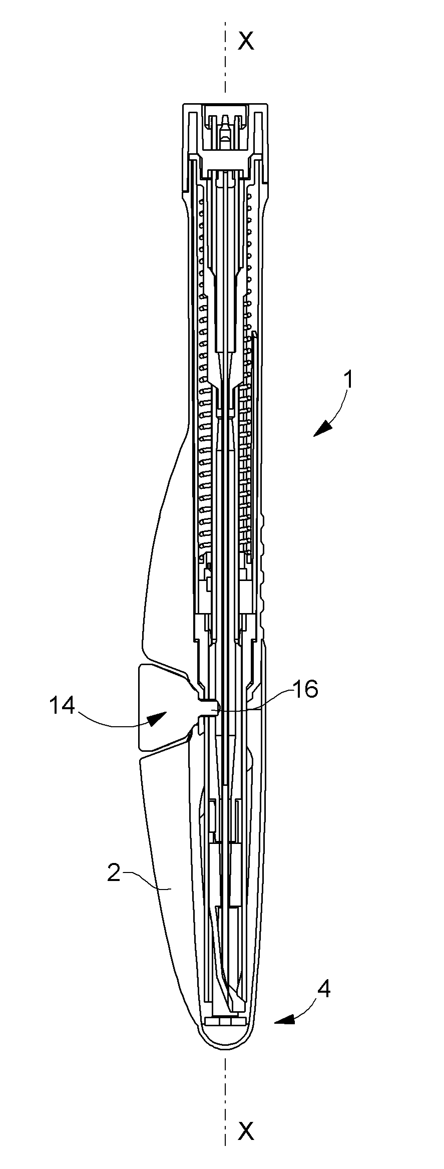
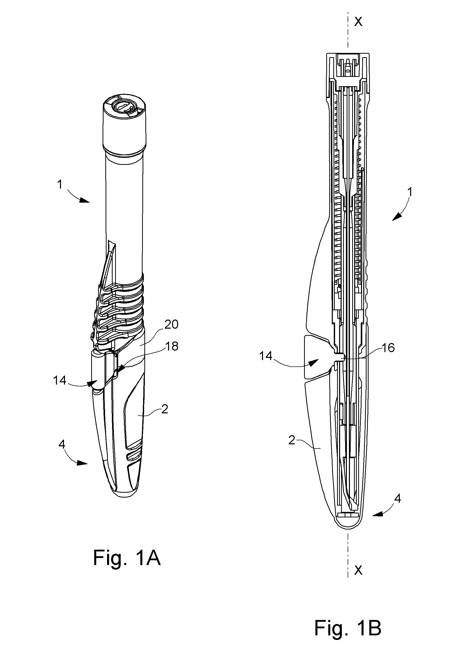
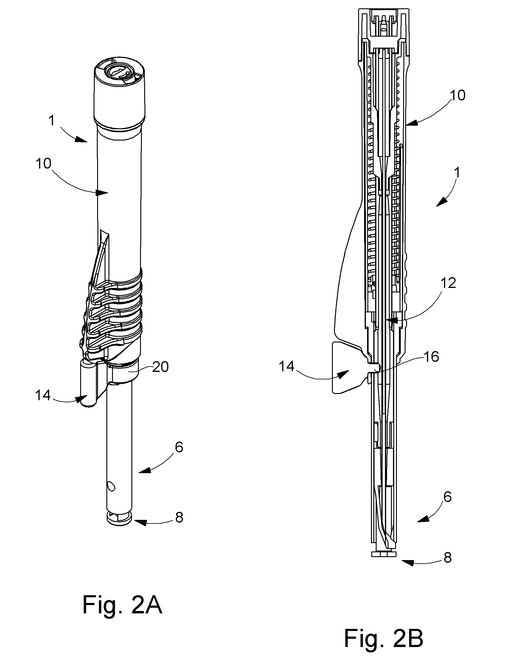
[0086]One starts by removing the back injection device according to the invention from its secondary packaging (not shown). Designated as a whole by the general reference numeral 1, the back injection device includes first (see FIGS. 1A and 1B) a cap 2 that covers its distal end 4. In order to carry out the back-injection, this cap 2 must first of all be removed by exerting thereon a slight traction force along the longitudinal axis X-X of said back injection device 1. During this movement, a sheath 6 extended at the distal end thereof by a retaining element 8 is uncovered (see FIGS. 2A and 2B), these two elements projecting from the main body 10 of back injection device 1. As will be seen in more detail hereafter, retaining element 8 is secured to secondary body 2 that extends coa...


PUM


Abstract

The invention concerns a device for back injecting an implant (30) into the skin (22) of a subject, said device (1) include a hollow main body (10), to which a hollow needle (28) is fixed into which the implant (30) is introduced, a secondary body (12; 114) coaxially arranged inside the main body (10) and surrounding the needle (28) and a piston rod (88) able to slide coaxially inside said hollow needle (28) and whose position relative to said needle (28) remains unchanged when the back injection device (1) is pressed against the subject's skin (22) to allow the needle (28) to penetrate said subject's skin and when the secondary body (12) retracts inside the main body (10), the piston rod (88) penetrating the interior of the hollow needle (28) to hold the implant (30) at the required depth in the subject's skin (22) during withdrawal of the hollow needle (28) from the subject's skin (22), during which the secondary body (12; 114) exits the main body (10), characterized in that it includes means for the elastic return of the secondary body (12) from the main body (10).

Description

[0001]This is a National Phase Application in the United States of International Patent Application No. PCT / EP2005 / 012825 filed Dec. 1, 2005, which claims priority on European Patent Applications No. 04028413.5, 04028411.9 and 04028412.7, all filed Dec. 1, 2004. The entire disclosures of the above patent applications are hereby incorporated by reference.FIELD OF THE INVENTION[0002]The present invention concerns an injection device and, in particular, a device for the intramuscular or subcutaneous injection of an active pharmaceutical principle in the solid or semisolid state, usually called an implant. More generally, the invention applies to the injection of a solid body for human or animal use such as for example electronic chips used for identifying a living being.BACKGROUND OF THE INVENTION[0003]Implant back injection devices of the type with which the present invention is concerned conventionally comprise a main hollow body, secured to a hollow needle into which the implant to ...

Claims


Application Information

Patent Timeline
IPC IPC(8): A61M5/00
CPCA61M37/0069A61M31/007
Inventor AUBERT, CHRISTOPHECHERIF-CHEIKH, ROLANDRIMLINGER, THIERRYBONACCI, FABRICEBARNEAUD, SERGESMETHAM, GRANT TIMOTHY LEWISDIXON, JULIAN RICHARDYOUNG, MATTHEW EGERTON
Owner IPSEN PHARMA SAS
Why Eureka
Try Eureka