Hydraulic Lift Structure

a technology of hydraulic lift and hydraulic cylinder, which is applied in the direction of agricultural machines, servomotors, adjusting devices, etc., can solve the problems of higher manufacturing cost of the working vehicle (the hydraulic lift structure), and achieve the effects of preventing the malfunction of the hydraulic cylinder, improving the supplying and discharging efficiency of the working fluid, and improving the maintenance characteristi

Inactive Publication Date: 2008-10-16
YANMAR CO LTD
View PDF3 Cites 2 Cited by
  • Summary
  • Abstract
  • Description
  • Claims
  • Application Information

AI Technical Summary

Benefits of technology

[0019]In the hydraulic lift structure in accordance with the present invention, since the oil reservoir of the working fluid for the hydraulic cylinder is provided in the boundary portion between the transmission case and the hydraulic cylinder case in such a manner as to be isolated from the inner portion of the transmission case, it is possible to prevent the dust garbage or the like generated by the mechanical gear mechanism or the like within the transmission case from mixing into the hydraulic cylinder case, and it is possible to prevent the malfunction of the hydraulic cylinder or the like caused by the dust garbage or the like mentioned above. Further, it is not necessary to arrange the filters (the line filter and the like) for removing the dust garbage or the like, and it is possible to improve the supplying and discharging efficiency of the working fluid. Further, it is not necessary to drain the oil from the hydraulic cylinder case at a time of detaching the hydraulic cylinder case from the transmission case, and it is possible to improve a maintenance characteristic.
[0020]Further, in the hydraulic lift structure in accordance with the present invention, since the oil reservoir is attached in such a manner that the concave portion is formed in the upper portion of the transmission case, and the hydraulic cylinder case covers the upper side of the concave portion, it is not necessary to set the additional member in the transmission case or the like, it is possible to reduce a manufacturing cost, and it is possible to omit an installation space of the member. Further, it is possible to effectively utilize a dead space in an upper portion of the transmission case, and it is possible to reinforce the upper portion of the transmission case.
[0021]Further, in the hydraulic lift structure in accordance with the present invention, since the oil reservoir is used as the oil reservoir of the working fluid for the working machine, the dust garbage or the like does not mix into a hydraulic system device of the working machine, it is possible to prevent the malfunction of the device caused by the dust garbage or the like, and it is possible to prevent the oil path pressure from being lowered by the filters so as to improve the supplying and discharging efficiency of the working fluid. Further, since the working fluid does not mix with the lubricating oil within the transmission case, it is possible to suppress the ascent of the oil temperature of the working fluid, and it is possible to suppress a deterioration of the working fluid.

Problems solved by technology

Further, a manufacturing cost of the working vehicle (the hydraulic lift structure) becomes higher by arranging the line filter.

Method used


Image

  • Hydraulic Lift Structure
  • Hydraulic Lift Structure
  • Hydraulic Lift Structure

Examples


Embodiment Construction

[0032]Next, a description will be given of an embodiment in accordance with the present invention.

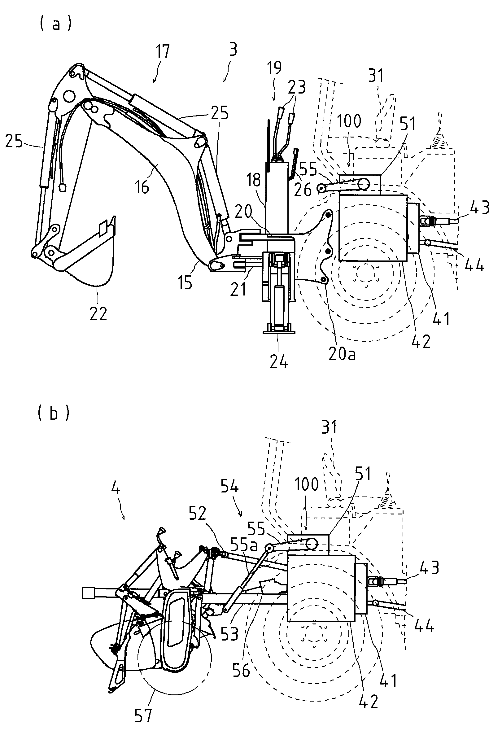
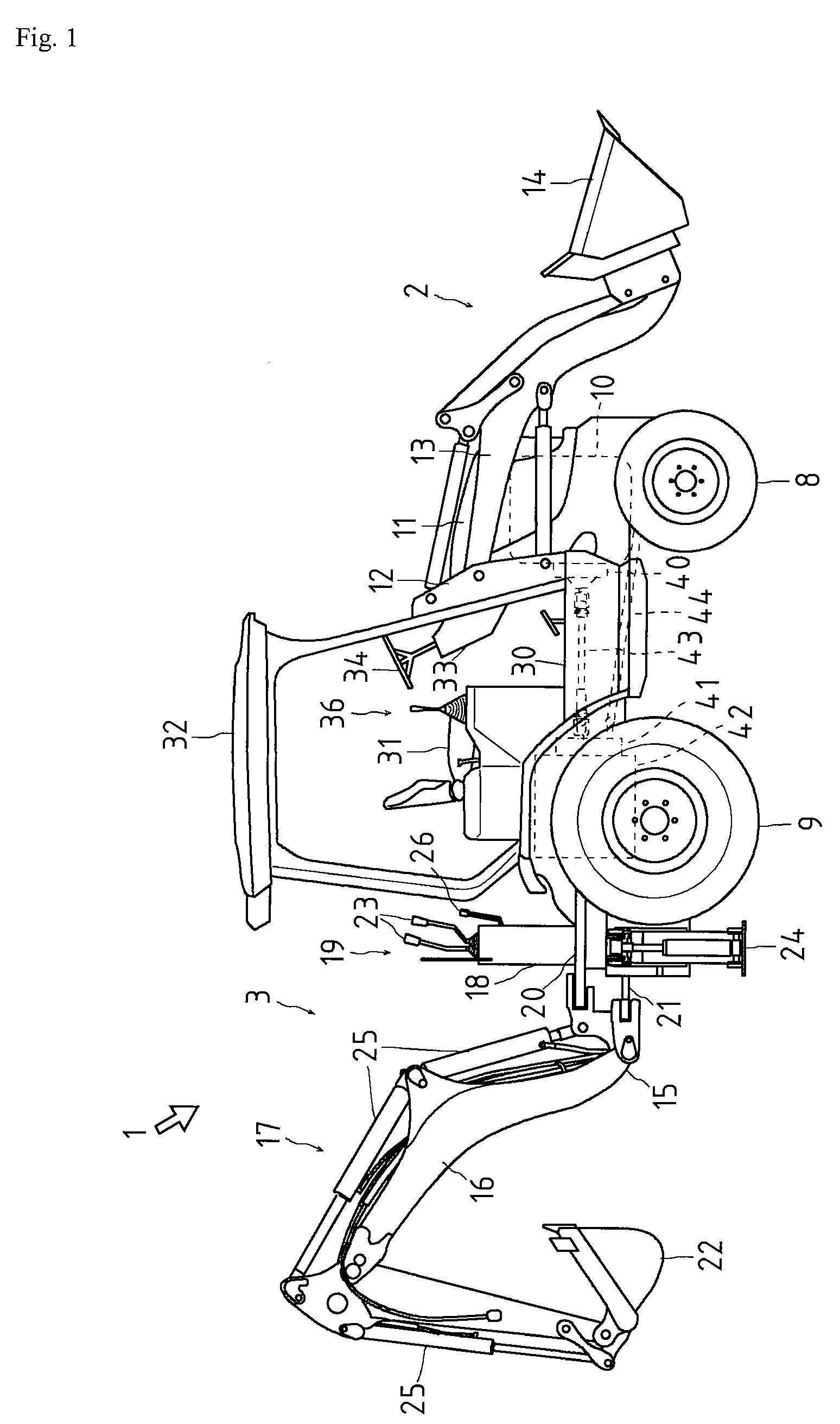
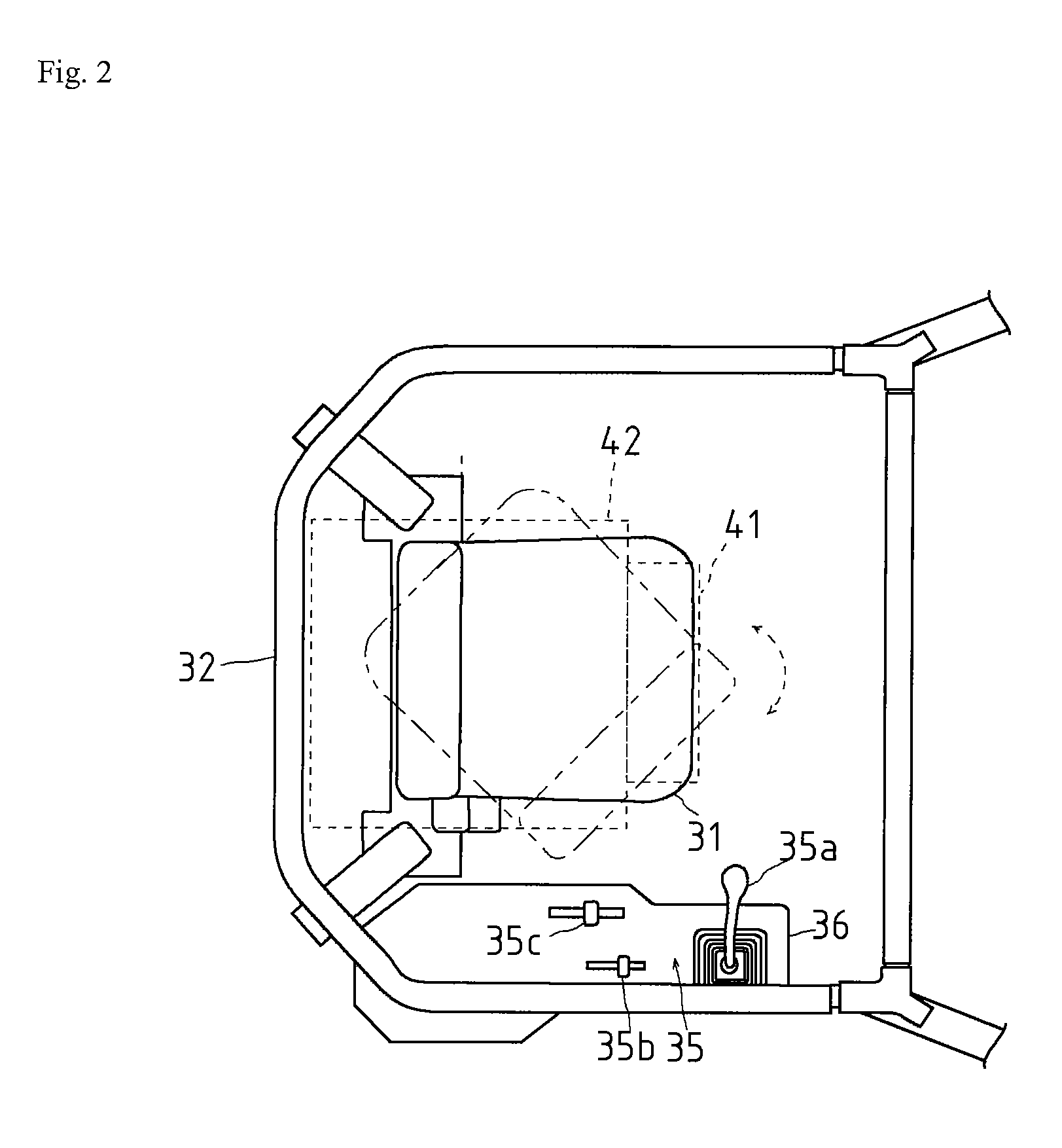
[0033]A working vehicle 1 in the present embodiment is structured such that a front loader 2 is arranged in a front side of a machine body, and a back hoe 3 structured such as to be replaceable is arranged in a rear side of the machine body. Further, the working vehicle 1 is structured such that a rotary power tiller 4 serving as a working machine moved up and down by a hydraulic cylinder 50 mentioned below is arranged in place of the back hoe 3.

[0034]First, a description will be given below of a whole structure of the working vehicle 1 in accordance with the present embodiment.

[0035]As shown in FIGS. 1 and 2, the working vehicle 1 in accordance with the present embodiment is structured as a back hoe loader, and the front loader 2 serving as a loading apparatus and the back hoe 3 are installed (hereinafter, a direction in which the front loader 2 is arranged is set to a front side of th...


PUM


Abstract

An object of the invention is to propose a hydraulic lift structure which prevents a malfunction of a hydraulic cylinder or the like and improves a supplying and discharging efficiency of a working fluid. In a hydraulic lift structure formed by arranging a hydraulic cylinder case internally provided with a hydraulic cylinder for moving up and down a working machine (a rotary power tiller) in an upper portion of a transmission case of a working vehicle, an oil reservoir of a working fluid for the hydraulic cylinder is provided in a boundary portion between the transmission case and the hydraulic cylinder case in such a manner as to be isolated from an inner portion of the transmission case.

Description

BACKGROUND OF THE INVENTION[0001]1. Field of the Invention[0002]The present invention relates to a hydraulic lift structure, and more particularly to a layout structure of an oil reservoir of a working fluid which is supplied to and discharged from a hydraulic cylinder case (a hydraulic cylinder) moving up and down a working machine, in a working vehicle structured such that the working machine is replaceable and detachable such as a back hoe, a rotary power tiller or the like.[0003]2. Background Art[0004]The working vehicle such as a tractor or the like is structured such that the working machine such as the rotary power tiller or the like is arranged in a rear side of a machine body, and a fertilizer applicator, a seeding machine or the like can be replaced and attached in addition to the rotary power tiller or the like, in accordance with a working content. For example, as the tractor in which the unit such as the rotary power tiller or the like is arranged in a rear side of the ...

Claims


Application Information

Patent Timeline
Patent Type & Authority Applications(United States)
IPC IPC(8): F01B25/04A01B63/10F15B1/26F16H57/02F16H57/023
CPCA01B63/1013E02F3/6273E02F3/964E02F9/0858E02F9/0883E02F9/166E02F9/2004Y10S180/90
Inventor YAMASHITA, MASAAKI
Owner YANMAR CO LTD
Why Eureka
Try Eureka