Brake Shoe

a technology of brake shoes and cooling steps, which is applied in the direction of brake components, friction linings, mechanical equipment, etc., can solve the problems of reducing productivity and the inability of the covering layer to improve productivity, and achieves high mass-productivity, low cost, and high reliability.

Inactive Publication Date: 2008-10-16
ADVICS CO LTD
View PDF3 Cites 6 Cited by
  • Summary
  • Abstract
  • Description
  • Claims
  • Application Information

AI Technical Summary

Benefits of technology

[0011]An object of this invention is to provide a brake shoe of which the lining is less likely to peel off the shoe body, which can ...

Problems solved by technology

In the method disclosed in Patent document 3, although the time for forming and bonding can be shortened by cooling the shoe body, the addition of the cooling step lowers productivity.
of...

Method used


Image

  • Brake Shoe
  • Brake Shoe
  • Brake Shoe

Examples


Embodiment Construction

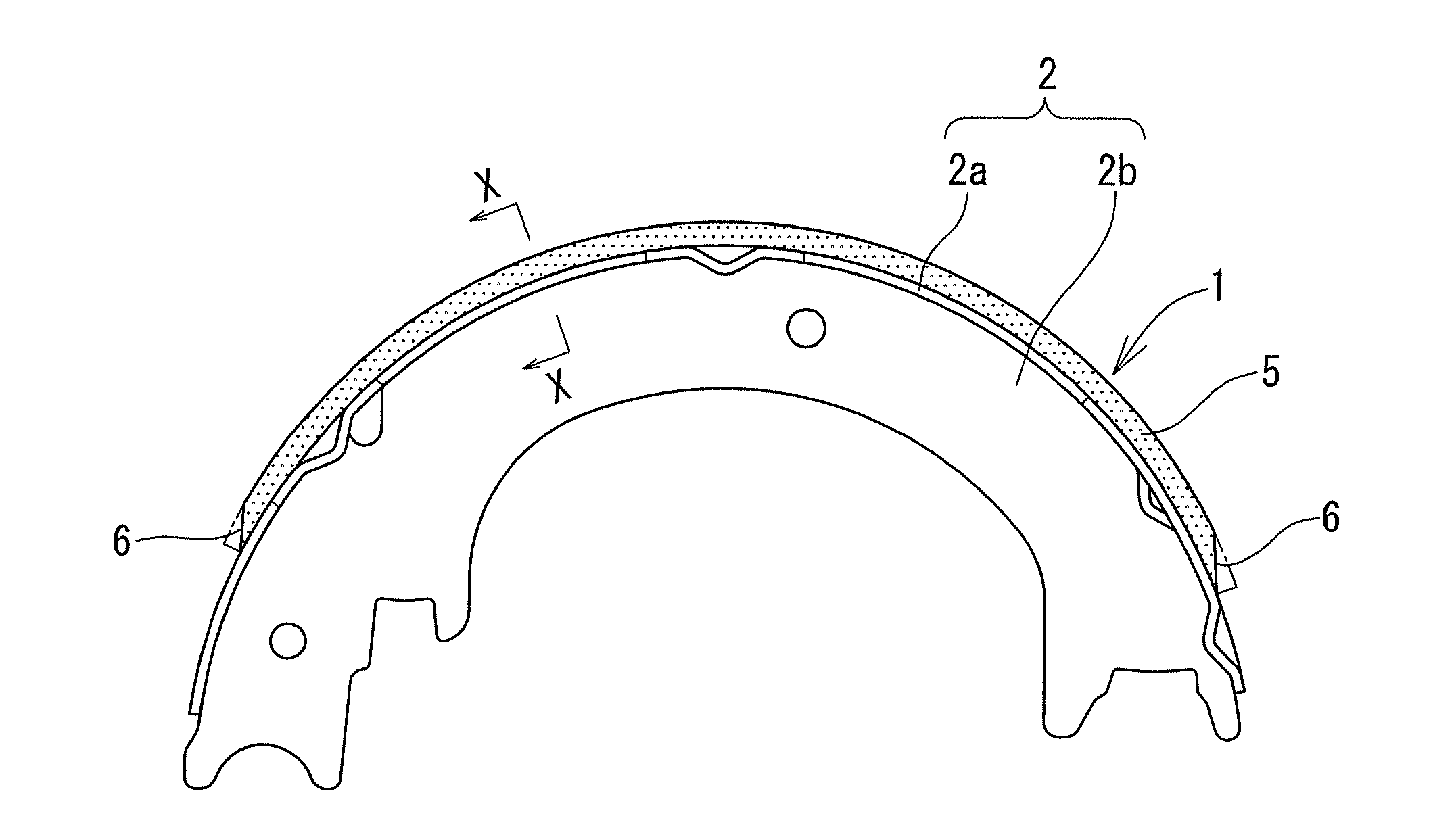
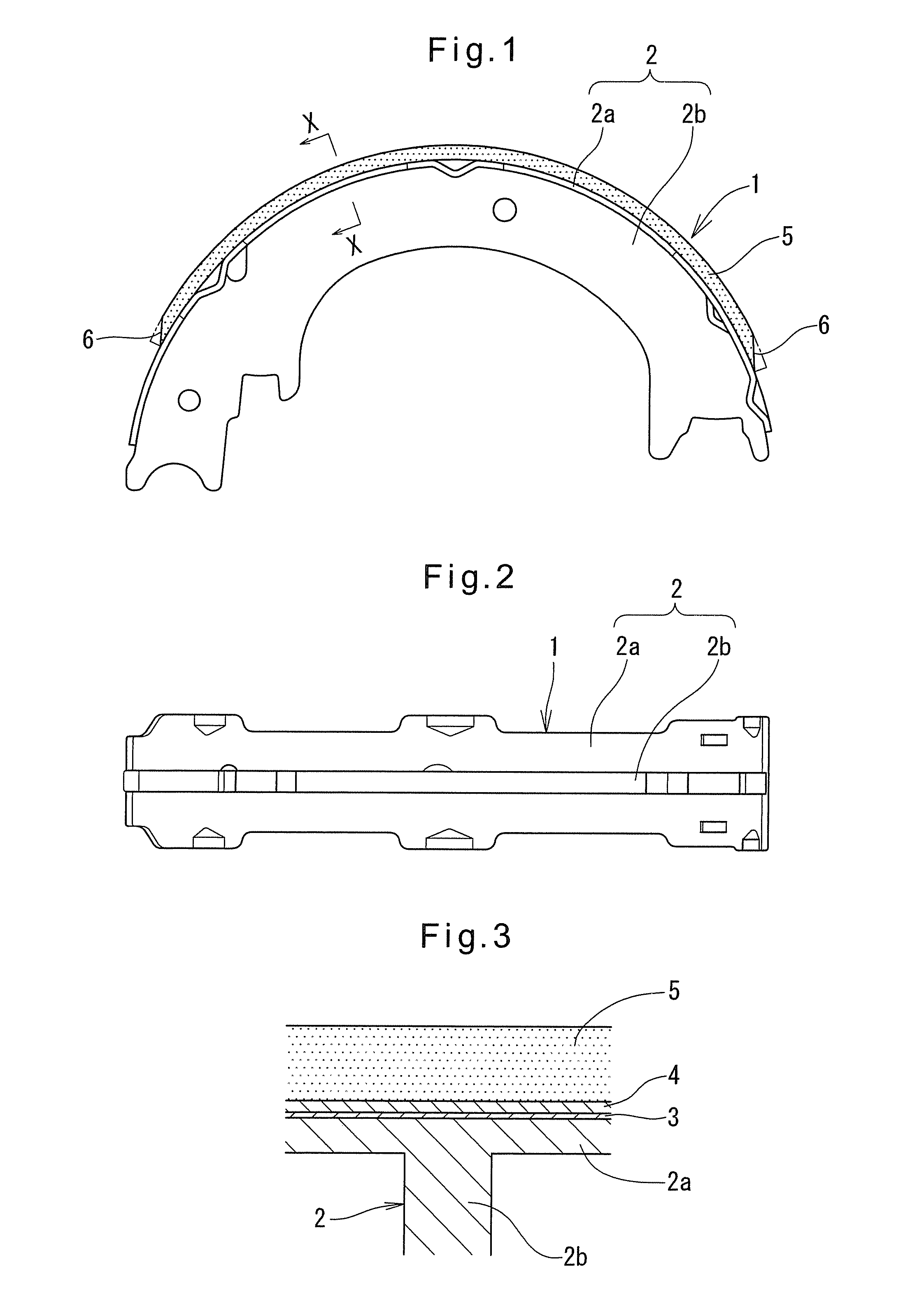
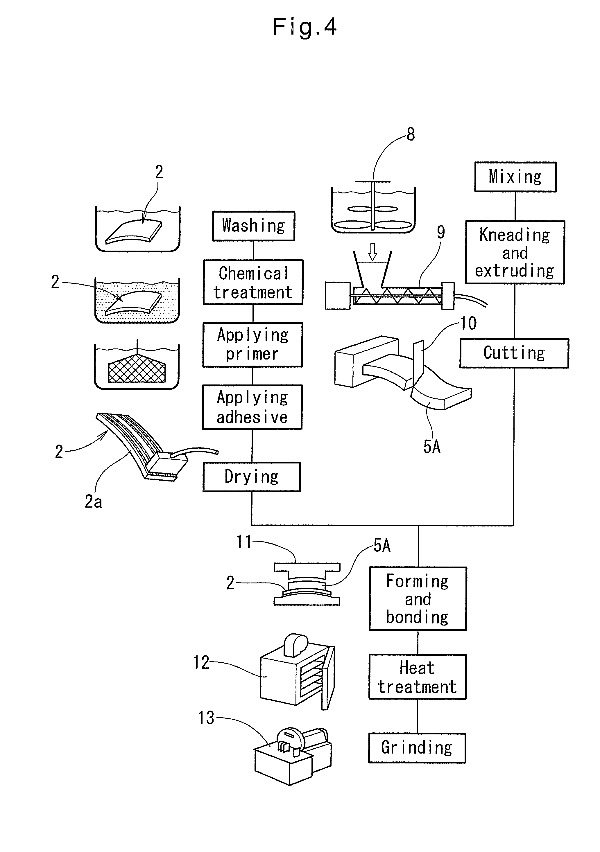
[0025]Now the brake shoe embodying the present invention is described with reference to FIGS. 1 to 4. As is apparent from FIGS. 1 and 2, the brake shoe shown is one used in a drum brake. This brake shoe 1 comprises a shoe body 2, and an arcuate lining 5 fixed to the outer periphery of the shoe body 2 through a bonding layer 3 and an interlayer 4 shown in FIG. 3. The shoe body 2 comprises an arcuately bent rim 2a, and a web 2b joined to the inner periphery of the rim 2a. The lining 5 is bonded to the outer periphery of the rim 2a.

[0026]The bonding layer 3 is made of a thermosetting resin, typically a phenolic resin. The interlayer 4 is a thin layer, about 50 to 500 μm thick, made e.g. of nitrile rubber (NBR). The interlayer 4 does not become ebonite, and remains elastic after the lining has been hardened by heat treatment.

[0027]The lining 5 is made of a composition which is a mixture of a substrate, lubricant, friction adjuster, filler and binder. The substrate, lubricant, friction ...


PUM


Abstract

A brake shoe is proposed which includes a lining containing a rubber of the type which becomes ebonite when vulcanized. An elastic interlayer is disposed between the lining and an adhesive layer through which the lining is bonded to the shoe body. The interlayer serves as a stress relief layer, thereby preventing the lining from peeling off the shoe body when the brake shoe is subjected to thermal history.

Description

CROSS REFERENCE TO RELATED APPLICATIONS[0001]This application is based on and claims priority under 35 U.S.C. sctn. 119 with respect to Japanese Patent Application No. 2007-21736 filed on Jan. 31, 2007, the entire content of which is incorporated herein by reference.BACKGROUND OF THE INVENTION[0002]This invention relates to a brake shoe which is suitable as a brake shoe of a vehicle drum brake, and particularly a brake shoe which is high in mass-productivity, inexpensive, and high in performance and reliability.[0003]Brake shoes for use e.g. in vehicle drum brakes comprise a shoe body and a lining adhesively bonded to the shoe body. Such a lining comprises a substrate, lubricant, friction adjuster, binder and filler.[0004]Such brake shoes and technologies relating thereto are disclosed e.g. in JP Patent publications 2003-156090A, 3677235B, 10-196695A and 2001-163993A (which are hereinafter referred to as Patent documents 1-4, respectively). Patent document 1 disclose a composition f...

Claims


Application Information

Patent Timeline
IPC IPC(8): F16D65/04
CPCF16D69/04F16D2069/005F16D2069/0466F16D2069/0475F16D2069/0491
Inventor KOBAYASHI, MASAAKI
Owner ADVICS CO LTD
Why Eureka
Try Eureka