Engine Assembly for an Aircraft Comprising an Engine as Well as an Engine Mounting Structure for Such an Engine

a technology of engine and mounting structure, which is applied in the direction of machines/engines, mechanical equipment, transportation and packaging, etc., can solve the problems of large space occupation of the exchanger in the secondary annular duct, significant disturbance of aerodynamic flow at the wing, and inability to optimise the use of fluid output from this second outlet, etc., to achieve the advantage of aerodynamic performance, reduce the size of the box, and simplify the geometry of the box significantly

Active Publication Date: 2008-10-16
AIRBUS OPERATIONS (SAS)
View PDF3 Cites 35 Cited by
  • Summary
  • Abstract
  • Description
  • Claims
  • Application Information

AI Technical Summary

Benefits of technology

[0015]Thus, this arrangement according to the invention advantageously does not require a second outlet pipe passing through the box of the rigid structure of the pylon, because the second air outlet is below the lower structural element of this box, as is also the case for the exchanger when the engine is designed to be suspended under the wing. Consequently, the safety of the engine assembly and the ease of assembly of the heat exchanger system are improved. Furthermore, the position of the second outlet specific to this invention advantageously implies that air output from this outlet no longer disturbs the flow at the wing. Therefore aircraft performances can be improved compared with performances encountered with embodiments according to prior art.
[0026]Finally, it should be noted that the block projecting downwards from the box and only extending over a short longitudinal length of the rigid structure makes it easy to pass ducts or similar elements through this lower structural block. Therefore this possibility provided for pylon equipment facilitates access to the aft part of the rigid structure, which in prior art required to pass through the box to which access is relatively difficult.

Problems solved by technology

This particular arrangement of the second outlet has a number of disadvantages, for instance it is necessary to provide an outlet pipe passing vertically through the rigid structure of the pylon to bring the second outlet above the rigid structure, which creates obvious safety problems, and layout difficulties related to the poor access to the box forming the rigid structure.
Furthermore, with such an arrangement, the relatively hot air exits from the second outlet close to the aircraft wing, which can significantly disturb aerodynamic flow at the wing.
Nevertheless, the specific location of this second outlet near the forward end of the engine communicating with the exchanger cold air inlet makes it impossible to optimise use of fluid output from this second outlet.
Furthermore, the presence of the exchanger in the secondary annular duct occupies a large amount of space.

Method used


Image

  • Engine Assembly for an Aircraft Comprising an Engine as Well as an Engine Mounting Structure for Such an Engine
  • Engine Assembly for an Aircraft Comprising an Engine as Well as an Engine Mounting Structure for Such an Engine
  • Engine Assembly for an Aircraft Comprising an Engine as Well as an Engine Mounting Structure for Such an Engine

Examples


Embodiment Construction

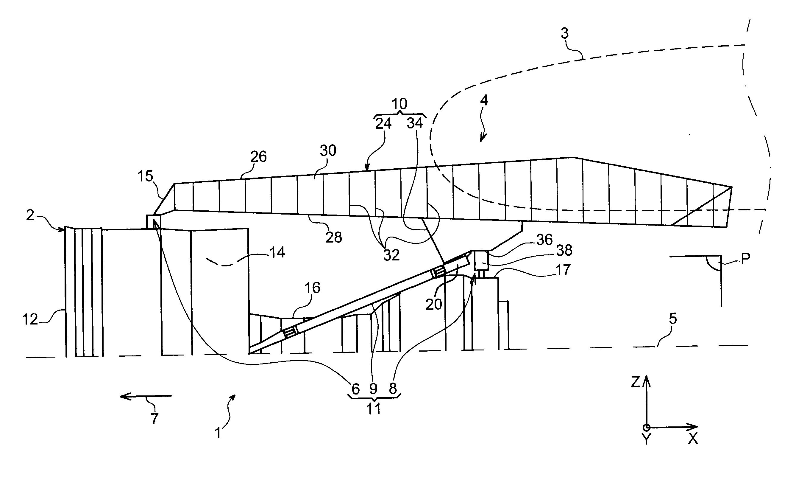
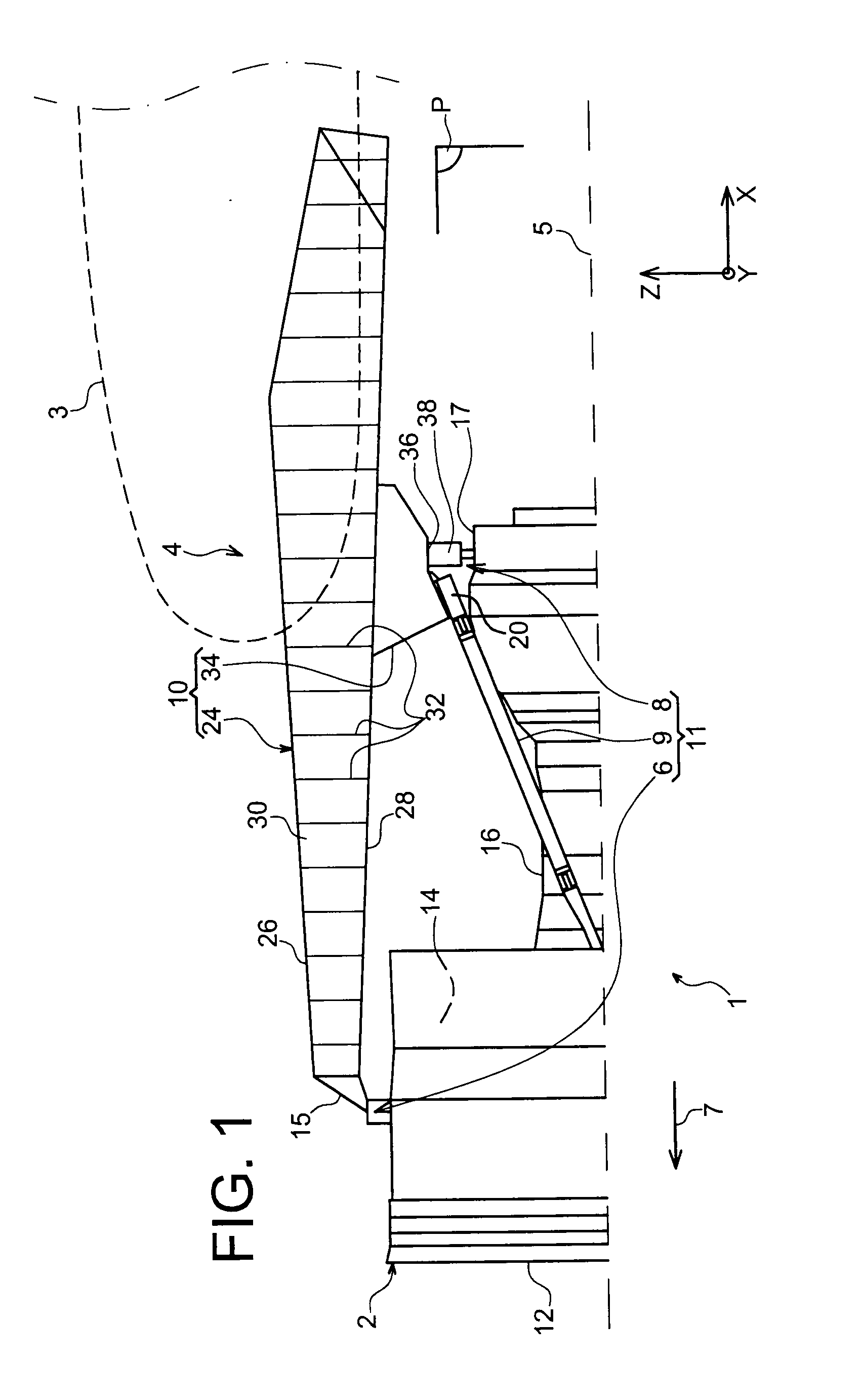
[0041]FIG. 1 shows an aircraft engine assembly 1 designed to be fixed under a wing 3 of this aircraft, this assembly 1 being provided with a suspension pylon 4, and in the form of a preferred embodiment of this invention.

[0042]Globally, the engine assembly 1 is composed of a turbojet 2 and the suspension pylon 4, the suspension pylon in particular being provided with a rigid structure 10 and a mounting system 11 composed of a plurality of engine suspensions 6, 8 and a device for resisting thrusts 9 generated by the turbojet 2, therefore the mounting system 11 being inserted between the engine and the above-mentioned rigid structure 10. For guidance, it should be noted that the assembly 1 is surrounded by a pod (not shown in this figure), and that the suspension pylon 4 comprises another series of suspensions (not shown) to assure suspension of this assembly 1 under the aircraft wing.

[0043]Throughout the following description, by convention, X refers to the longitudinal direction of ...


PUM


Abstract

An aircraft engine assembly including an engine, an engine suspension pylon, and a heat exchanger system including a second outlet located between the box and the engine, aft from the aft engine suspension. Furthermore, the exchanger in the heat exchanger system is at least partially arranged inside an aft aerodynamic fairing of the suspension pylon, the aft aerodynamic fairing being located entirely aft from the aft engine suspension.

Description

TECHNICAL DOMAIN[0001]This invention relates in general to the domain of engine suspension pylons designed to be inserted between an aircraft wing and an engine, and more particularly to an engine assembly comprising such a suspension pylon.[0002]The invention may be used on any aircraft type, for example equipped with turbojets or turboprops.[0003]This type of suspension pylon is also called an EMS (Engine Mounting Structure), for example that can be used to suspend a turboengine below the aircraft wing, or to fit this turboengine above this wing.STATE OF PRIOR ART[0004]Such a suspension pylon is designed to form an attachment interface between an engine such as a turbojet and an aircraft wing. It transmits forces generated by its associated turbojet to the structure of this aircraft, and it also enables routing of fuel, electrical, hydraulic and air systems between the engine and the aircraft.[0005]The pylon comprises a rigid structure, also called the primary structure, frequentl...

Claims


Application Information

Patent Timeline
Patent Type & Authority Applications(United States)
IPC IPC(8): B64D27/00
CPCB64D27/26B64D2027/268B64D2033/024Y02T50/672F01D25/28F02C7/20F01D25/24Y02T50/60
Inventor JOURNADE, FREDERICBRUNET, ROBERT
Owner AIRBUS OPERATIONS (SAS)
Why Eureka
Try Eureka