Power storage device and semiconductor device provided with the power storage device

a technology of power storage device and semiconductor device, which is applied in the direction of secondary cell servicing/maintenance, sustainable manufacturing/processing, instruments, etc., can solve the problems of not being able to charge the plurality of power storage device, not being able to adequately charge electromagnetic wave attenuation, etc., and achieves short period of time and high electric power

Inactive Publication Date: 2008-10-16
SEMICON ENERGY LAB CO LTD
View PDF6 Cites 148 Cited by
  • Summary
  • Abstract
  • Description
  • Claims
  • Application Information

AI Technical Summary

Benefits of technology

[0007]However, in an example of a power storage device described in Patent Document 1, when an electromagnetic wave with high electric field intensity is supplied to the power storage device for supplying high electric power in a short period of time, effects on the human body are concerned. In addition, as for supply of an electromagnetic wave with high electric field intensity to a power storage device for supplying high electric power in a short period of time, there is a regal regulation on transmission of an electromagnetic wave with a certain amount or more of electric field intensity, magnetic field intensity, or power flux density per unit time.

Problems solved by technology

Moreover, when a power storage device is charged, especially when a plurality of power storage devices is charged, they might not be sufficiently charged with electromagnetic wave attenuation.
For example, there has been a problem in that if voltage applied to a battery included in the power storage device is not higher than a certain value, charging is not performed in some cases, and accordingly, it is hard to charge the plurality of power storage devices.
There has been a problem in that when charging of a power storage device is completed or interrupted for some cause, measures such as prevention measures against overcharging and stop of supply of unnecessary electric power through an electromagnetic wave are taken on a power feeder, under a condition that electric power is intermittently supplied from the power feeder through the electromagnetic wave.

Method used


Image

  • Power storage device and semiconductor device provided with the power storage device
  • Power storage device and semiconductor device provided with the power storage device
  • Power storage device and semiconductor device provided with the power storage device

Examples


embodiment mode 1

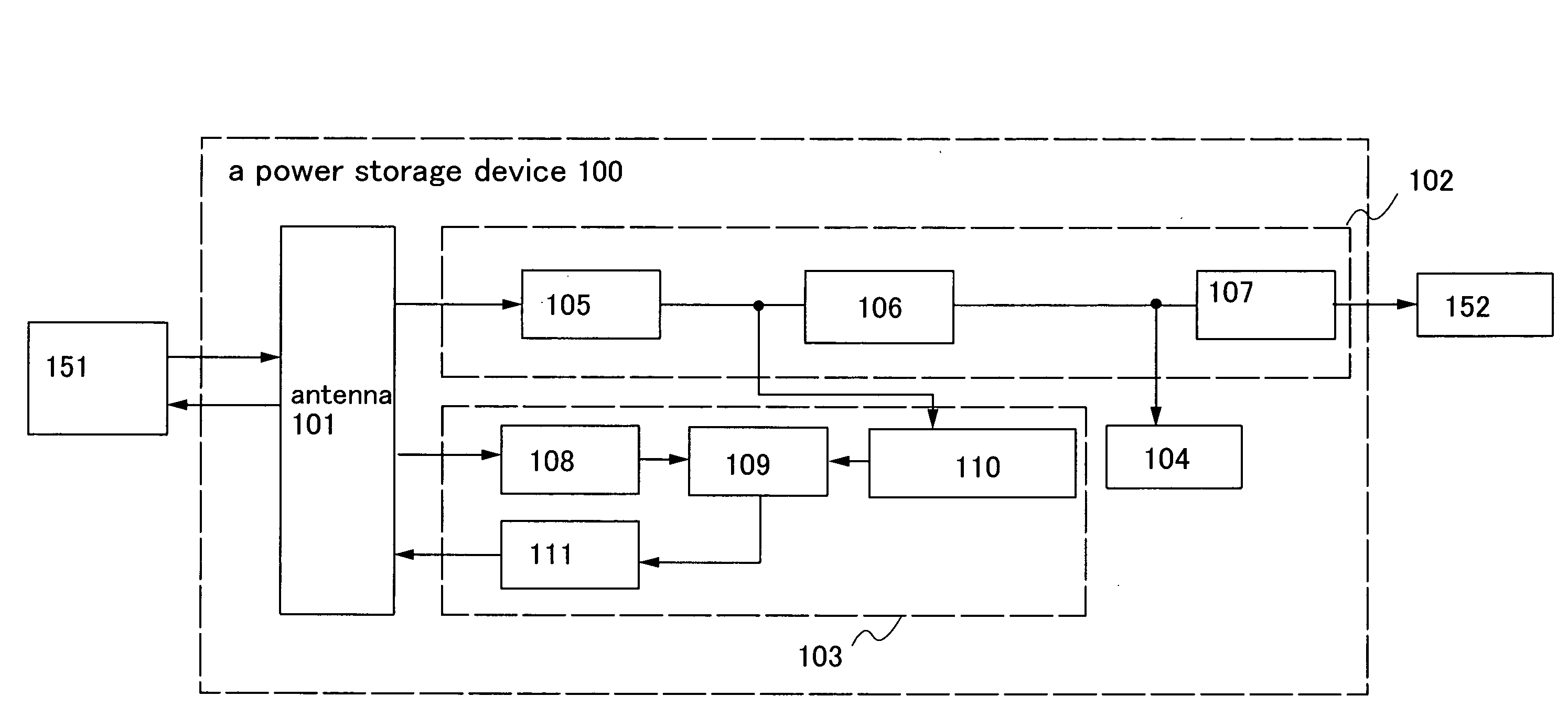
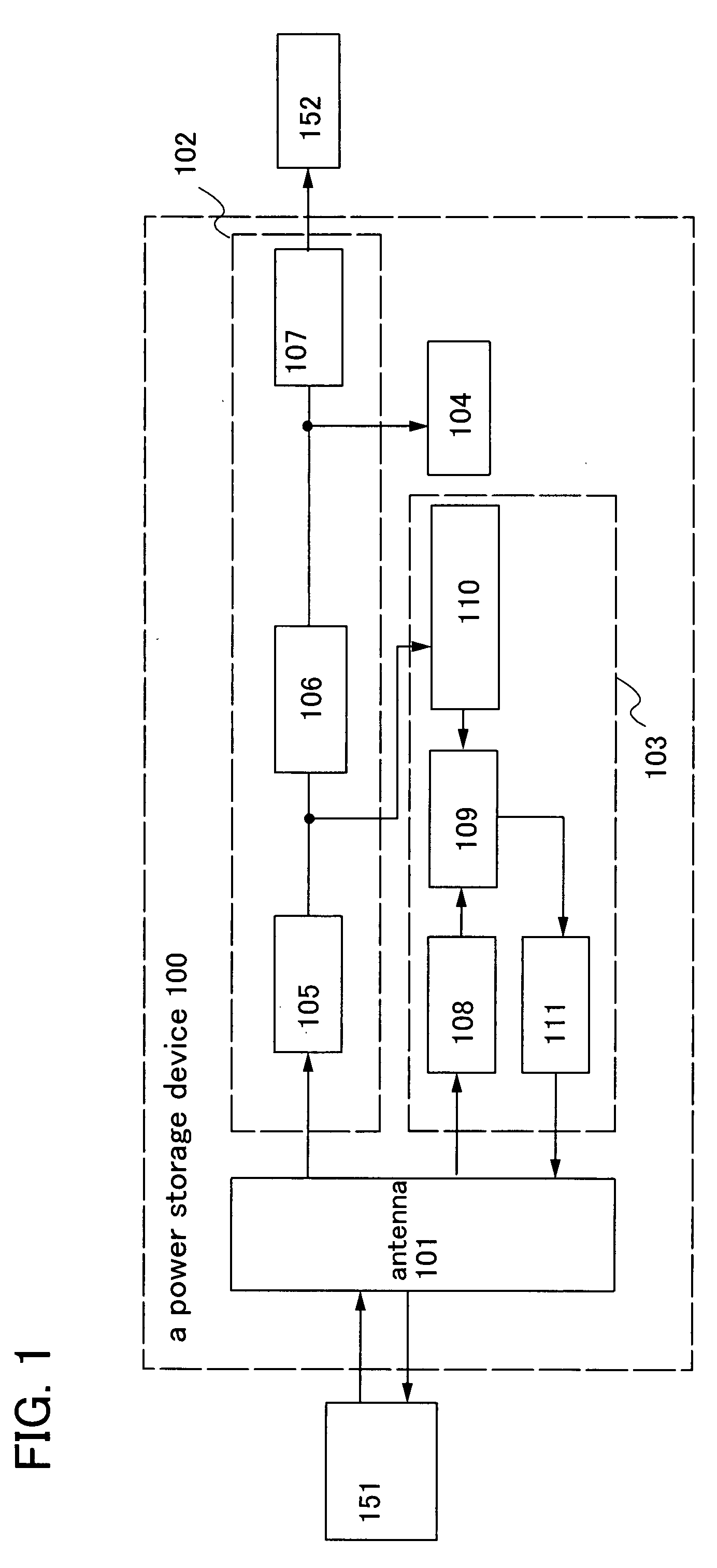
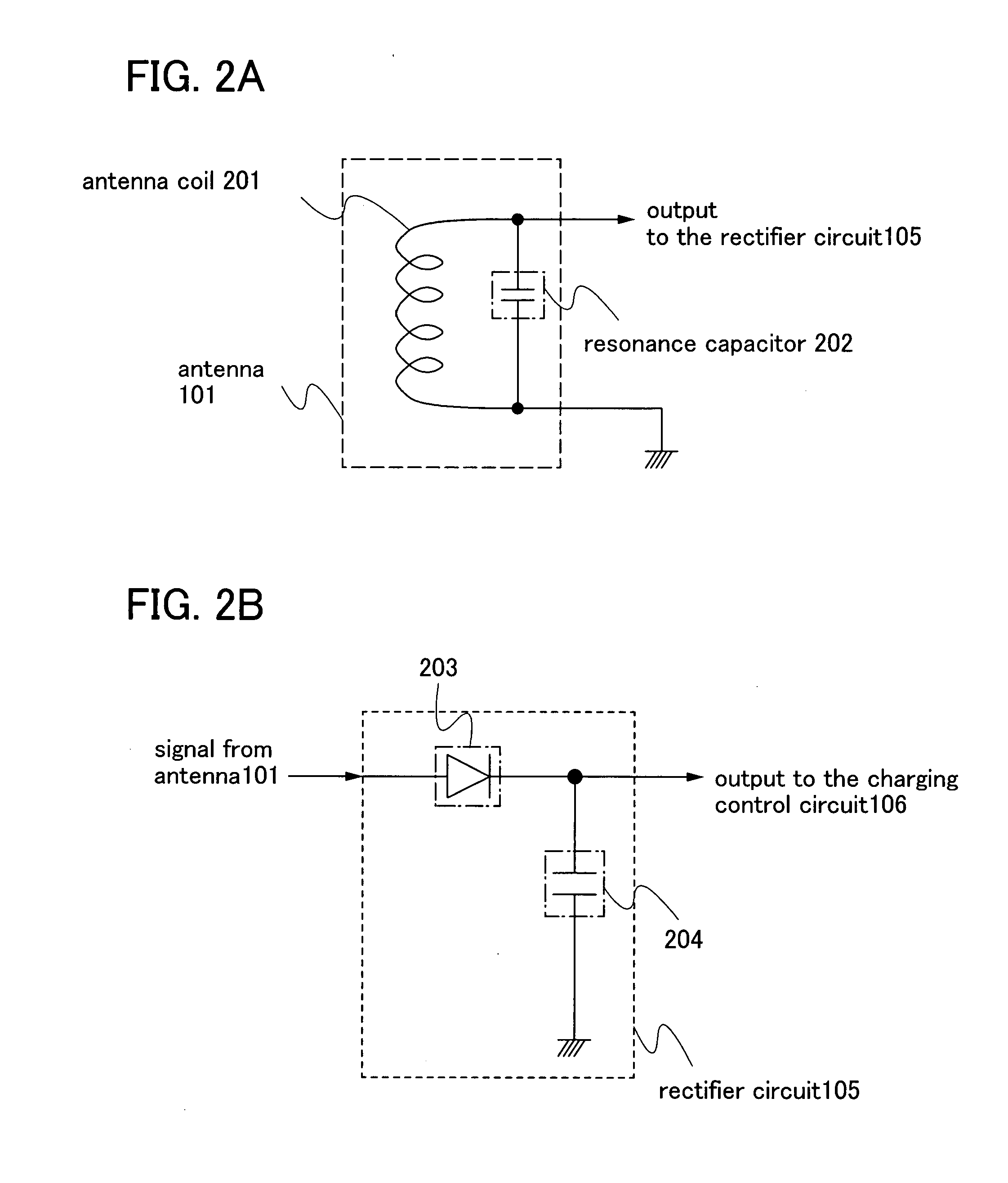
[0057]One structural example of a power storage device of the present invention will be explained with reference to block diagrams shown in FIG. 1 and FIGS. 2A and 2B. It is to be noted that the case where the power storage device is charged by a power feeder that is a power supply means will be explained in this embodiment mode.

[0058]A power storage device 100 shown in FIG. 1 includes an antenna 101, a power supply portion 102, a charging determination portion 103, and a battery 104. Electric power is supplied to the power storage device 100 by a power feeder 151, and the electric power stored in the battery 104 in the power storage device 100 is supplied to a load 152. The power supply portion 102 includes a rectifier circuit105 that rectifies an electromagnetic wave inputted to the antenna 101, a charging control circuit 106 that controls charging of the battery 104 with electric power from the rectifier circuit 105, and a power supply circuit 107 for controlling supply of the el...

embodiment mode 2

[0107]In this embodiment mode, a structure in which a charging management circuit is included in the power storage device described in above Embodiment Mode 1 will be explained with reference to drawings. It is to be noted that, in the drawings used in this embodiment mode, same parts as those in Embodiment Mode 1 are denoted by the same reference numerals.

[0108]It is to be noted that a “charging management circuit” in this embodiment mode refers to a circuit that is dedicated to managing charging / discharging of a battery when using the battery. When using a battery, it is generally necessary to manage the charging / discharging of the battery. When charging a battery, it is necessary to perform charging while at the same time monitoring the charged state of the battery in order to prevent overcharging. For the battery used in the present invention, a dedicated circuit is necessary when conducting management of charging.

[0109]The power storage device in this embodiment mode will be ex...

embodiment mode 3

[0125]In this embodiment mode, a structure in which a signal processing circuit is provided as a load in the power storage device described in above Embodiment Mode 1 will be explained with reference to a drawing. It is to be noted that, in some cases, in the drawing used in this embodiment mode, same parts as those in Embodiment Mode 1 are denoted by the same reference numerals.

[0126]One structural example of a power storage device of the present invention in this embodiment mode will be explained with reference to a block diagram shown in FIG. 14. It is to be noted that, in this embodiment mode, a signal processing circuit is included in the power storage device. Therefore, in this embodiment mode, the case in which the power storage device is used as a semiconductor device and the semiconductor device is used as an RFID will be explained.

[0127]A semiconductor device 1400 in FIG. 14 includes an antenna 101, a power supply portion 102, a charging determination portion 103, a batter...


PUM


Abstract

An object is to provide a power storage device provided with a battery that is a power storage means, for safe and accurate supply of electric power in a short period of time for drive power supply voltage without checking remaining capacity of the battery or changing batteries with deterioration over time of the battery for drive power supply voltage. The power storage device is provided with a battery that is a power storage means as a power supply for supplying electric power and a counter circuit for counting charging time of the power storage means. An electromagnetic wave with electric field intensity, magnetic field intensity, and power flux density per unit time which are transmitted from a power feeder are controlled, and the power storage means is efficiently charged using the electromagnetic wave in a short period of time.

Description

BACKGROUND OF THE INVENTION[0001]1. Field of the Invention[0002]The present invention relates to a power storage device. In particular, the present invention relates to a power storage device which is charged with electric power through an electromagnetic wave. Furthermore, the present invention relates to a charging system using a power storage device provided with an antenna and a power feeder which supplies electric power to the power storage device through an electromagnetic wave.[0003]A “power storage device” mentioned in this specification refers to a general device which stores electric power by an electromagnetic wave transmitted from an external power supply device (power feeder). In addition, a battery which stores power by wireless reception of an electromagnetic wave is referred to as a wireless battery (RF battery: Radio Frequency Battery).[0004]2. Description of the Related Art[0005]Various electronic appliances are coming into wide use, and a wide variety of products ...

Claims


Application Information

Patent Timeline
Patent Type & Authority Applications(United States)
IPC IPC(8): H02J7/00
CPCH01M10/0436H01M10/44H02J7/042H02J17/00Y02B40/90H02J7/045H01F38/14H02J7/025H03D9/00H04B5/0037Y02E60/12H02J50/12H02J50/20H02J50/23H02J50/80H02J7/007Y02E60/10H02J7/04Y02B40/00Y02P70/50H02J50/402H02J7/35H02J7/0071H02J7/00712H02J7/00714
Inventor OSADA, TAKESHI
Owner SEMICON ENERGY LAB CO LTD
Why Eureka
Try Eureka