System and Method for Controlling a Hysteretic Mode Converter

a voltage converter and hysteretic mode technology, applied in the field of voltage conversion, can solve the problems of introducing unwanted frequency components into the power signal, switching frequency may negatively affect the operation of the electronic device, switching frequency and harmonics containing these audible frequencies may produce nois

Active Publication Date: 2008-10-16
TEXAS INSTR INC
View PDF9 Cites 82 Cited by
  • Summary
  • Abstract
  • Description
  • Claims
  • Application Information

AI Technical Summary

Benefits of technology

[0010]An advantage of an embodiment is that control of the switching frequency may be afforded. Furthermore, it may be possible to specify the precision of the control over the switching frequency. A single design may be used to provide loose control or tight control over the switching frequency by simply specifying a few control parameters and with no modifications to the design.
[0011]A further advantage of an embodiment is that the control over the switching frequency may be independent of manufacturing process, device aging, operating temperature, and so forth.

Problems solved by technology

The conversion of electrical power from a first voltage level to a second voltage level may introduce an unwanted frequency component in the power signal at the second voltage level.
In some cases, the switching frequency may negatively affect the operation of the electronic device.
Switching frequencies and harmonics containing these audible frequencies may produce noise that may be noticeable as humming, clicking, buzzing, and so forth, for instance.
However, PWM control may require a relatively complex feedback control system to ensure converter stability, therefore incurring greater development and manufacturing costs.

Method used


Image

  • System and Method for Controlling a Hysteretic Mode Converter
  • System and Method for Controlling a Hysteretic Mode Converter
  • System and Method for Controlling a Hysteretic Mode Converter

Examples


Embodiment Construction

[0022]The making and using of the embodiments are discussed in detail below. It should be appreciated, however, that the present invention provides many applicable inventive concepts that can be embodied in a wide variety of specific contexts. The specific embodiments discussed are merely illustrative of specific ways to make and use the invention, and do not limit the scope of the invention.

[0023]The embodiments will be described in a specific context, namely a boost mode converter, with the boost mode converter being used to provide backlighting in a display application. The invention may also be applied, however, to other forms of converters, such as a buck mode converter, buck-boost mode converter, and so forth. The converters may be used in a wide range of applications wherein there is a need to convert voltages from a first potential level to a second potential level.

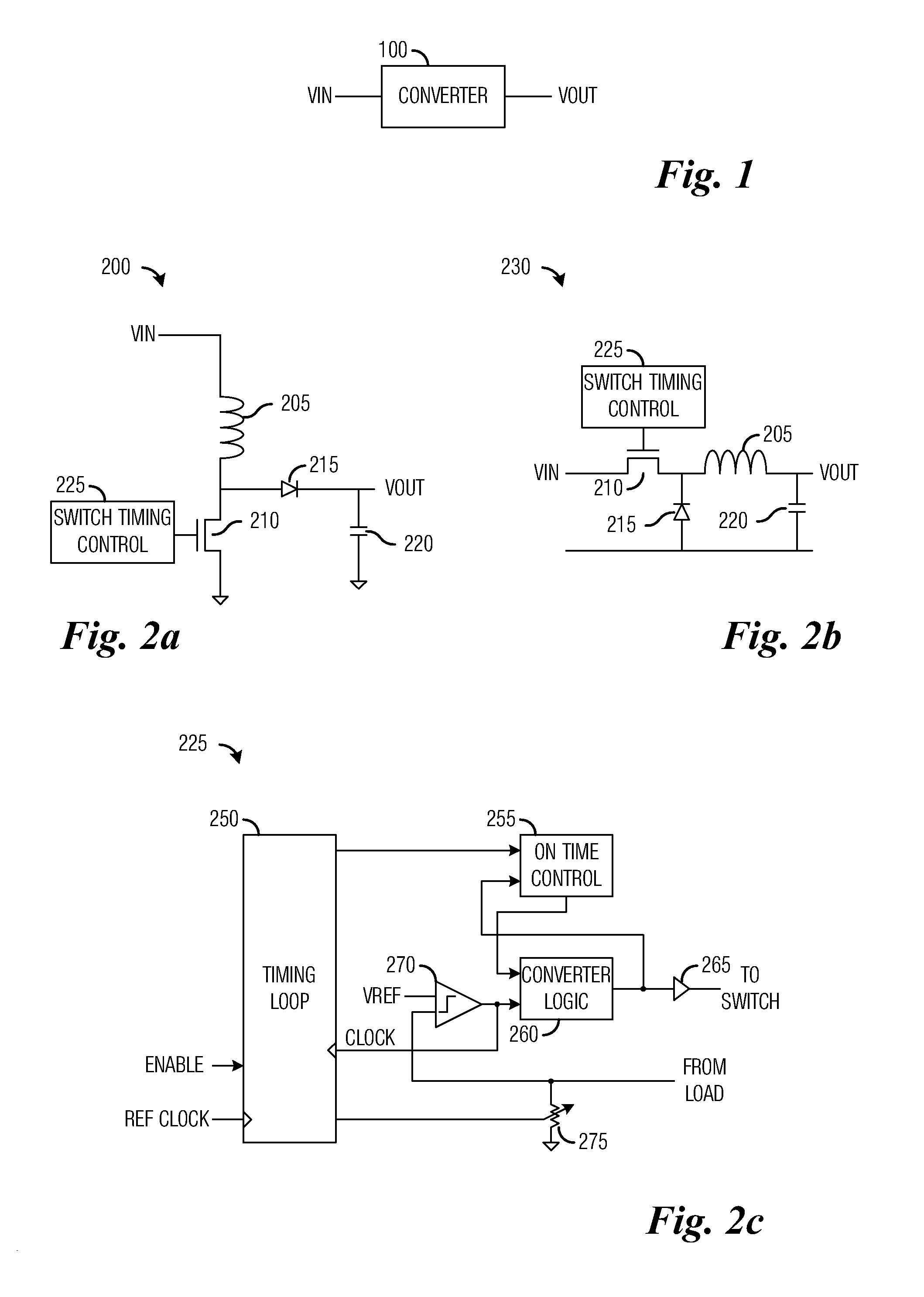
[0024]With reference now to FIG. 1, there is shown a diagram illustrating a high-level view of a converter 100....


PUM


Abstract

A system and method for controlling a conversion frequency of a hysteretic mode voltage converter. A digital control loop comprises a timing measure unit having a first input coupled to a reference clock and a second input coupled to a clock based on a switching of the switching of the converter, and an on time adjust unit coupled to the timing measure unit. The timing measure unit counts a number of clock ticks of a clock signal provided by the clock occurring during a period of time specified by a number of clock ticks of a reference clock signal provided by the reference clock. The on time adjust unit adjusts an on time control signal based on the count of the number of clock ticks of the clock signal to alter a frequency of the switching.

Description

[0001]This application claims the benefit of U.S. Provisional Application No. 60 / 868,820, filed on Dec. 6, 2006, entitled “Digital Control for Hysteretic Converter,” and also claims the benefit of U.S. Provisional Application No. 60 / 974,645, filed on Sep. 24, 2007, entitled “System and Method for Controlling a Hysteretic Mode Converter,” which applications are hereby incorporated herein by reference.TECHNICAL FIELD[0002]The present invention relates generally to a system and method for voltage conversion, and more particularly to a system and method for controlling a conversion frequency of a hysteretic mode voltage converter.BACKGROUND[0003]In modern day electronics, a single electronic device may require multiple forms of electrical power, such as alternating current and direct current. Additionally, the electronic device may make use of several different voltage levels. For example, in a personal computer, there may be a need for +3.3 V, −5 V, +5 V, and +12 V to provide different...

Claims


Application Information

Patent Timeline
Patent Type & Authority Applications(United States)
IPC IPC(8): G05F1/00
CPCH02M3/1563H02M2001/0012H02M1/0012
Inventor LINDEBERG, JONNE JALMAR SEBASTIANKONNAIL, GEORGE VINCENTILIASEVITCH, STEPAN
Owner TEXAS INSTR INC
Why Eureka
Try Eureka