Thin film magnetic head, head gimbal assembly, head arm assembly, magnetic disk device and method of forming thin film magnetic head

a thin film magnetic head and head arm technology, applied in the direction of instruments, heads with metal sheet cores, data recording, etc., can solve the problems of thermal protrusion, remained mask layer possibly reducing the reliability of the thin film magnetic head, and cracks in the cracks, so as to reduce the reliability of the element or variation in thermal protrusion for each element, the effect of effective suppression of thermal protrusion and reliability

Active Publication Date: 2008-10-16
TDK CORPARATION +1
View PDF2 Cites 4 Cited by
  • Summary
  • Abstract
  • Description
  • Claims
  • Application Information

AI Technical Summary

Benefits of technology

[0022]In the thin film magnetic head and the method of forming the same, and the head gimbal assembly, head arm assembly, and magnetic disk device of an embodiment of the invention, the two return yoke layers (first return yoke layer and second return yoke layer) are formed on the trailing side of the main magnetic pole layer, and the recess formed in the first return yoke layer is filled by the second return yoke layer. Thus, since the thermal expansion suppression layer can be provided on a surface having no recess, for example, a possibility of a crack in the thermal expansion suppression layer can be eliminated. Moreover, since there is no possibility that a mask layer used in forming the thermal expansion suppression layer is remained in an area where the mask layer is normally to be removed, there is also no possibility of unnecessary remainder of the thermal expansion suppression layer, or an unpredictable residue of the mask layer. Thus, when a protective film is formed on the thermal expansion suppression layer, possibility of a crack can be eliminated in a portion where the protective film is formed on the unnecessary remainder of the thermal expansion suppression layer or the residue of the mask layer. As a result, reduction in reliability caused by a crack, or variation in thermal protrusion for each element due to the crack can be suppressed.
[0023]Here, when the second return yoke layer has a flat top surface above at least the recess of the first return yoke layer, difficulties as above hardly occur. Therefore, thermal protrusion can be effectively suppressed while keeping reliability.
[0024]When the second return yoke layer extends backward from a position retracted from the air bearing surface beyond a position where the recess is formed, only the first return yoke layer is exposed on the air bearing surface in the return yoke layers provided on the trailing side of the main magnetic pole layer. Thus, even if a step of planarizing a top of the second return yoke layer is conducted, there is no possibility of variation due to planarization in area exposed on the air bearing surface of the return yoke layer being provided on the trailing side of the main magnetic pole layer. Therefore, thermal protrusion can be suppressed while a write characteristic of the thin film magnetic head is kept constant.

Problems solved by technology

However, in the first measure, since metal having a large thermal expansion coefficient is used for the radiation layer, thermal protrusion may occur under the influence of surrounding temperature environment.
In addition, the radiation layer is not easily provided in the periphery of the thin film coil, leading to restriction in process.
However, the third measure is not preferable since various difficulties may occur as described below.
In this case, the remained mask layer possibly reduces reliability of the thin film magnetic head 400.

Method used


Image

  • Thin film magnetic head, head gimbal assembly, head arm assembly, magnetic disk device and method of forming thin film magnetic head
  • Thin film magnetic head, head gimbal assembly, head arm assembly, magnetic disk device and method of forming thin film magnetic head
  • Thin film magnetic head, head gimbal assembly, head arm assembly, magnetic disk device and method of forming thin film magnetic head

Examples


Embodiment Construction

[0051]Hereinafter, a preferred embodiment of the invention will be described in detail with reference to drawings.

[0052]Configurations of a thin film magnetic head 1 of an embodiment of the invention, a head gimbal assembly 2 mounted with the thin film magnetic head 1, head arm assembly 300, and magnetic disk device are described hereinafter with reference to FIGS. 1 to 18.

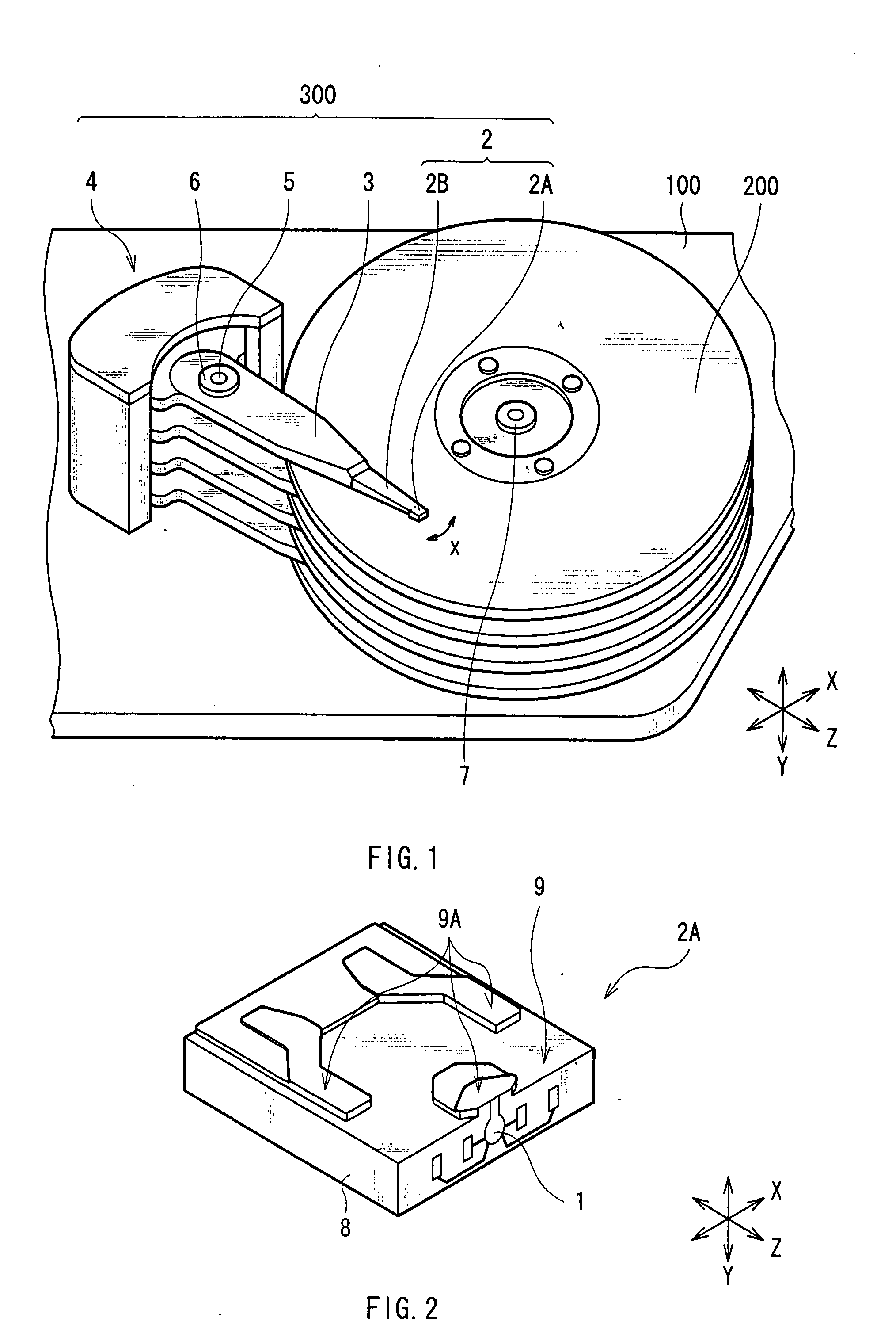
[0053]FIG. 1 is a perspective view showing an example of an internal configuration of the magnetic disk device according to the embodiment. For example, as shown in FIG. 1, the magnetic disk device has one or several (four in FIG. 1) magnetic recording medium 200 (for example, hard disk) capable of writing information, and a head arm assembly (HAA) 300 for writing information into the magnetic recording medium 200, and reading the information.

[0054]The HAA 300 has, for example, a head gimbal assembly (HGA) 2, an arm 3, and a drive section 4. The HGA 2 has a magnetic head slider (hereinafter, simply called “slider”...


PUM

PropertyMeasurementUnit
width W1aaaaaaaaaa
bevel angleaaaaaaaaaa
thicknessaaaaaaaaaa

Abstract

A thin film magnetic head is provided, in which thermal protrusion can be suppressed. The thin film magnetic head includes a main magnetic pole layer which conducts a magnetic flux into the recording medium so that the recording medium is magnetized in a direction perpendicular to a surface of the recording medium, a first return yoke layer provided in a trailing side of the main magnetic pole layer, and has a recess in a top surface, a second return yoke layer provided so as to fill at least the recess of the first return yoke layer, and a thermal expansion suppression layer provided in a trailing side of the second return yoke layer. Thus, since the thermal expansion suppression layer can be provided on a surface having no recess, a possibility of a crack in the thermal expansion suppression layer can be eliminated.

Description

BACKGROUND OF THE INVENTION[0001]1. Field of the Invention[0002]The present invention relates to a thin film magnetic head mounted with a magnetic transducer element and a method of forming the same, and a head gimbal assembly mounted with the thin film magnetic head, head arm assembly, and magnetic disk device.[0003]2. Related Art[0004]A magnetic disk device has been used for write and read of magnetic information (hereinafter, simply mentioned as information). For example, the magnetic disk device includes a magnetic disk for storing information, and a thin film magnetic head for writing information into the magnetic disk and reading information written in the magnetic disk. The magnetic disk is supported by a spindle of a spindle motor fixed to a housing, and rotated with the spindle as a center. On the other hand, the thin film magnetic head is formed on one side face of a magnetic head slider provided on one end of a suspension, and includes a magnetic write element having an a...

Claims


Application Information

Patent Timeline
Patent Type & Authority Applications(United States)
IPC IPC(8): G11B5/33G11B5/147G11B5/00
CPCG11B5/3133G11B5/3163
Inventor NARUSHIMA, SHINMATONO, NAOTOSAKAMOTO, TAKAMITSUKASAHARA, NORIAKIOTANI, KOICHI
Owner TDK CORPARATION
Why Eureka
Try Eureka