Label switching system

a label switching and label technology, applied in the field of label switching systems, can solve the problems of high-speed forwarding not being realized, the mounting space and the mounting cost, and the mounting space and the mounting cost, and achieve the effect of easy mounting and expanding the range of utilization

Inactive Publication Date: 2008-10-16
FUJITSU LTD
View PDF12 Cites 41 Cited by
  • Summary
  • Abstract
  • Description
  • Claims
  • Application Information

AI Technical Summary

Benefits of technology

[0067]According to the present invention, it is feasible to actualize MPLS on the packet router taking the architecture of mounting an IP / MPLS forwarder in an adapter at an egress for packets in terms of a mounting space and a mounting cost. As a result, MPLS utilizing the existing system architecture can be easily mounted.
[0068]Further, according to the present invention, when setting an explicit LSP, it is possible to attain routing elaborate enough to specify the ports or the port groups of the relay node and of the egress node. As a result, there is yielded a effect of expanding a range of utilizing an application making use of MPLS such as traffic engineering etc.

Problems solved by technology

According to this method, however, the CPU analyzes the packets, searches a routing table and edits a packet header, and therefore high-speed forwarding can not be actualized.
According to this method, when actualized based on the ATM switch, a common unit needs a new piece of hardware, and there is a problem in terms of a mounting space and a mounting cost as well.
This method needs an addition of functions to the adapter (the problems in terms of mounting is smaller than a change in the common unit), and, as in the example of architecture shown in FIG. 2, there exists the problem in terms of the mounting space and the mounting cost.
Further, both of the adapter at an ingress for the packets and the adapter at an egress for the packets terminate the IP / MPLS, which is redundant control.
This method needs an addition of functions to the adapter (the problems in terms of mounting is smaller than the change in the common unit), and, as in the examples of architecture shown in FIGS. 2 and 3, there exists the problem in terms of the mounting space and the mounting cost.
To be specific, the label distribution protocols of both of hop by hop routing and Explicit Routing are incapable of indicating an intra-system specified adapter or port, and it is therefore unfeasible to set the LSP in which the specified adapter of the egress node is a terminal.

Method used


Image

  • Label switching system
  • Label switching system
  • Label switching system

Examples


first embodiment

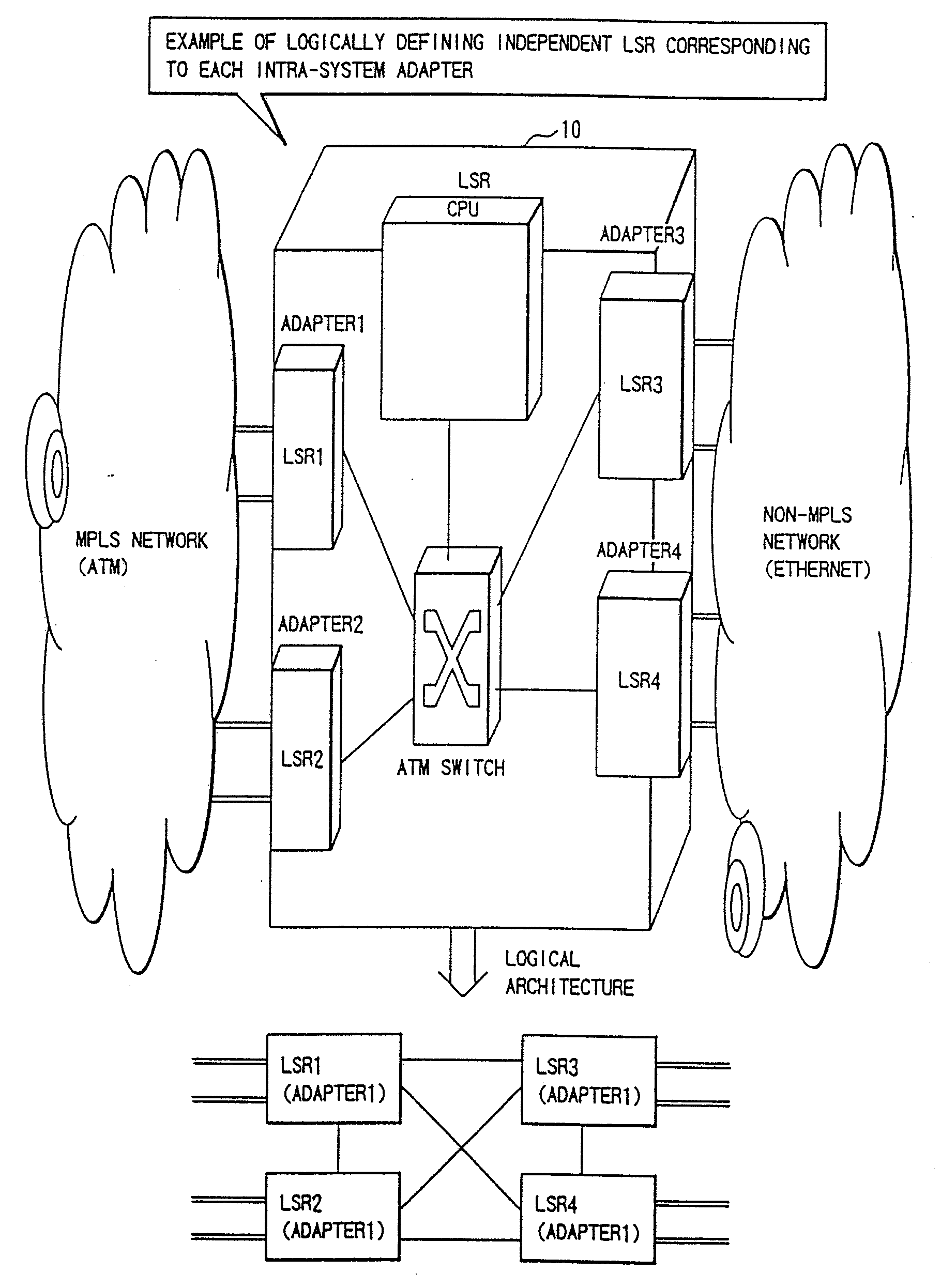
[0096]A label switching router (LSR) classified as a packet router in a first embodiment of the present invention, will be explained referring to FIGS. 8, 9 and 10 in combination. FIGS. 8 and 9 show an architecture of the LSR. FIG. 10 shows a processing flowchart.

[0097]A label switching router (LSR) 10 in the first embodiment adopts an architecture of logically mounting a plurality of LSRs in a system. The independent LSR is logically defined corresponding to each adapter (corresponding to a port group) within the LSR 10, and each adapter within the system is recognized as an independent LSR by other LSRs.

[0098]As shown in FIG. 8, an architecture of the LSR 10 is that adapters 1 and 2 are connected to an MPLS network (ATM), and adapters 3 and 4 are connected to a non-MPLS network (Ethernet). With respect to this LSR 10, LSR 1, LSR 2, LSR 3 and LSR 4 are defined as logical LSRs, and the respective LSRs are connected in full-mesh, corresponding to the adapters 1, 2, 3 and 4.

[0099]Base...

second embodiment

[0115]The label switch router (LSR) serving as a packet router in a second embodiment of the present invention will be described with reference to FIGS. 11, 12, 13 through 18, 19, 20 and 21 in combination. FIGS. 11 and 12 show an architecture of the label switch router (LSR). FIGS. 13 through 18 show examples of a variety of definitions of the protocols for the traffic engineering. FIGS. 19, 20 and 21 are flowcharts showing the processes.

[0116]A label switching router (LSR) 30 in the second embodiment takes such an architecture that the intra-system adapters can be specified.

[0117]As shown in FIG. 11, the LSR 30 has a database stored with various items of topology data of the network. The LSR 30 incorporates a function of flooding the topology data on the basis of the database, and a function of updating the database on the basis of the flooded topology data. Further, the LSR 30 has a label distributing function (LSO setting function) by which an explicit route is specified based on...

third embodiment

[0141]The label switching router (LSR) classified as the packet router in a third embodiment of the present invention, will be explained referring to FIGS. 22, 23, 24, and 25 in combination.

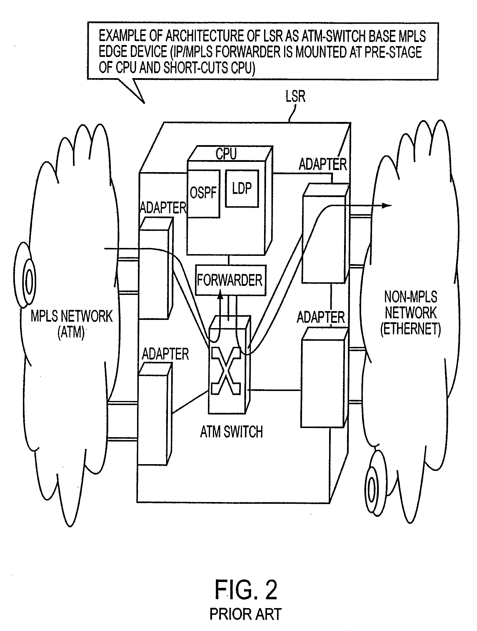
[0142]A label switching router (LSR) 40 in the third embodiment takes such an architecture that an egress adapter within the system is capable of executing internal shuttling. As shown in FIG. 22, the LSR 40 has, in the system architecture illustrated in FIG. 2, an addition of the following functions to one specified egress adapter. That is, these functions are a function (1) of setting a connection with other egress adapter via an ATM switch, a function (2) conducting IP forwarding to other adapters in addition to the intra-adapter ports (which uses the connection given in the item (1), and a function (3) of adding routing data to other adapters to a routing table that is referred in the item (2).

[0143]With these functions added, the setting of the explicit LSP can be actualized neither by chang...


PUM


Abstract

A packet router in a label switching system includes a logical router configuring module for logically dividing a label switching router (LSR) into a plurality of LSRs each having a label switching function, and a module for specifying, when setting a label switched path on the basis of an explicit route specified, a port or a port group of an egress node. With this construction, a label switching architecture in an ATM network for actualizing MPLS (label switching) can be mapped to an ATM-Switch base system architecture, and a granularity of function (Constraint Base Routing) of specifying a variety of routes provided by MPLS can be attained.

Description

BACKGROUND OF THE INVENTION[0001]The present invention relates generally to a label switching system, and more particularly to an explicit routing method and a packet router in this label switching system.[0002]The label switching is a key technology for actualizing an Intranet / Internet backbone oriented high-speed transfer, traffic load sharing and band control on a full scale. The label switching also functions to match a routing process at an IP level (Layer 3) with a switching process on a lower layer (Layer 2) where ATM, a frame relay, Ethernet etc are conducted, and perform packet forwarding (transmission, exchange and transfer) on Layer 2 according to [labels] attached to IP packets.[0003]Standardization of this label switching are now being promoted as MPLS (Multi Protocol Label Switching) by MPLS-WG of IETF (Internet Engineering Task Force). Further, ITU (International Telecommunication Union) also examines the use of MPLS in IP over ATM (IP / ATM) in the public network.[0004...

Claims


Application Information

Patent Timeline
Patent Type & Authority Applications(United States)
IPC IPC(8): H04L12/56H04L12/28H04L12/40H04L12/413H04L12/46H04L12/66H04L45/50
CPCH04L12/66H04L41/08H04L41/0823H04L45/10H04L45/507H04L45/60
Inventor SASAGAWA, YASUSHI
Owner FUJITSU LTD
Why Eureka
Try Eureka