Scan compression circuit and method of design therefor

a compression circuit and integrated circuit technology, applied in the direction of instruments, pulse techniques, computation using denominational number representation, etc., can solve the problems of increasing the number of xs per shift, significant part of the cost of electronic system design, manufacture and service,

Active Publication Date: 2008-10-16
SYNOPSYS INC
View PDF9 Cites 29 Cited by
  • Summary
  • Abstract
  • Description
  • Claims
  • Application Information

AI Technical Summary

Benefits of technology

[0025]Use of a selector in the direct observation modes ensures that any data of interest in any scan cell can be extracted from the respective scan chain and supplied (transparently through the compressor) to a tester. Such a selector may be configured with any number of direct observation modes, depending on the number of scan chains and the number of outputs of the compressor. Hence several embodiments support observability in two dimensions: any particular scan cell (in the space dimension) and any particular shift cycle (in the time dimension), thereby to provide granularity at the lowest level known to the current inventors.
[0026]Use of combinational logic in some embodiments of the selector allows control on a per-shift basis easily. Moreover, a completely combinational implementation of the selector is significantly simpler and uses fewer gates, than certain prior art selectors that use sequential elements. The scan-based circuit also includes a compressor which has several groups of input lines that are coupled to the selector. The selector supplies data from a given scan chain in the electronic device selectively to one or more lines in the group of input lines.

Problems solved by technology

Testing digital circuits accounts for a significant part of the cost to design, manufacture, and service electronic systems.
Scan unload compression techniques exploit the fact that error values appear more or less randomly, and only on a few scan chains at a time.
One issue with use of scan unload compression arises in the presence of unknown values (X) values.
However, recent designs can often have more than two Xs per shift which exceeds the X-tolerance that can be ensured by the method of FIG. 1B.
Several factors can contribute to increase the number of Xs per shift: (1) Increased functional complexity of recent designs results in extended usage of RAMs, which are X-sources for basic-scan ATPG.
(2) Aggressive timing of designs creates a large number of false paths that are modeled by X-ing out the values captured in scan cells during test application, thus also increasing the number of Xs.
Additionally, the current inventors note that in blocking out all Xs, some non-X values may also be blocked which can be problematic if some of the non-X values happen to be data that needs to be observed.
Rajski further states that if multiple X states occur, the error propagation paths can be blocked and the error may not be observed at all.
Accordingly, the current inventors note that both XDBIST and Rajski's technique suffer from the complexity and overhead of sequential elements.
Also, both are limited to only one X-avoiding data selection per load, whereas the profile of Xs changes with every shift cycle of the load.
Therefore, the current inventors believe that the selection of non-X data is too coarse, which can result in lower test quality and higher pattern count, i.e., lower compression.
Finally, XDBIST allows only a fraction of the scan chains to be observed during each unload, which can also result in lower test quality and higher pattern count, i.e., lower compression.
Depending on the tradeoff taken this can result in too much X-avoiding data, or too much masking of non-X data.

Method used


Image

  • Scan compression circuit and method of design therefor
  • Scan compression circuit and method of design therefor
  • Scan compression circuit and method of design therefor

Examples


Embodiment Construction

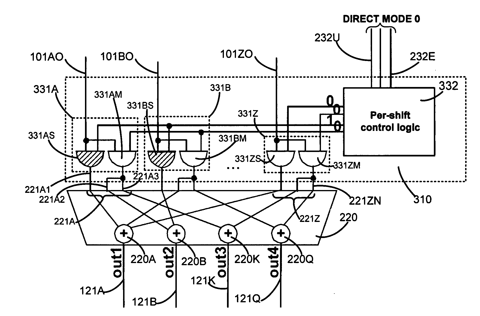
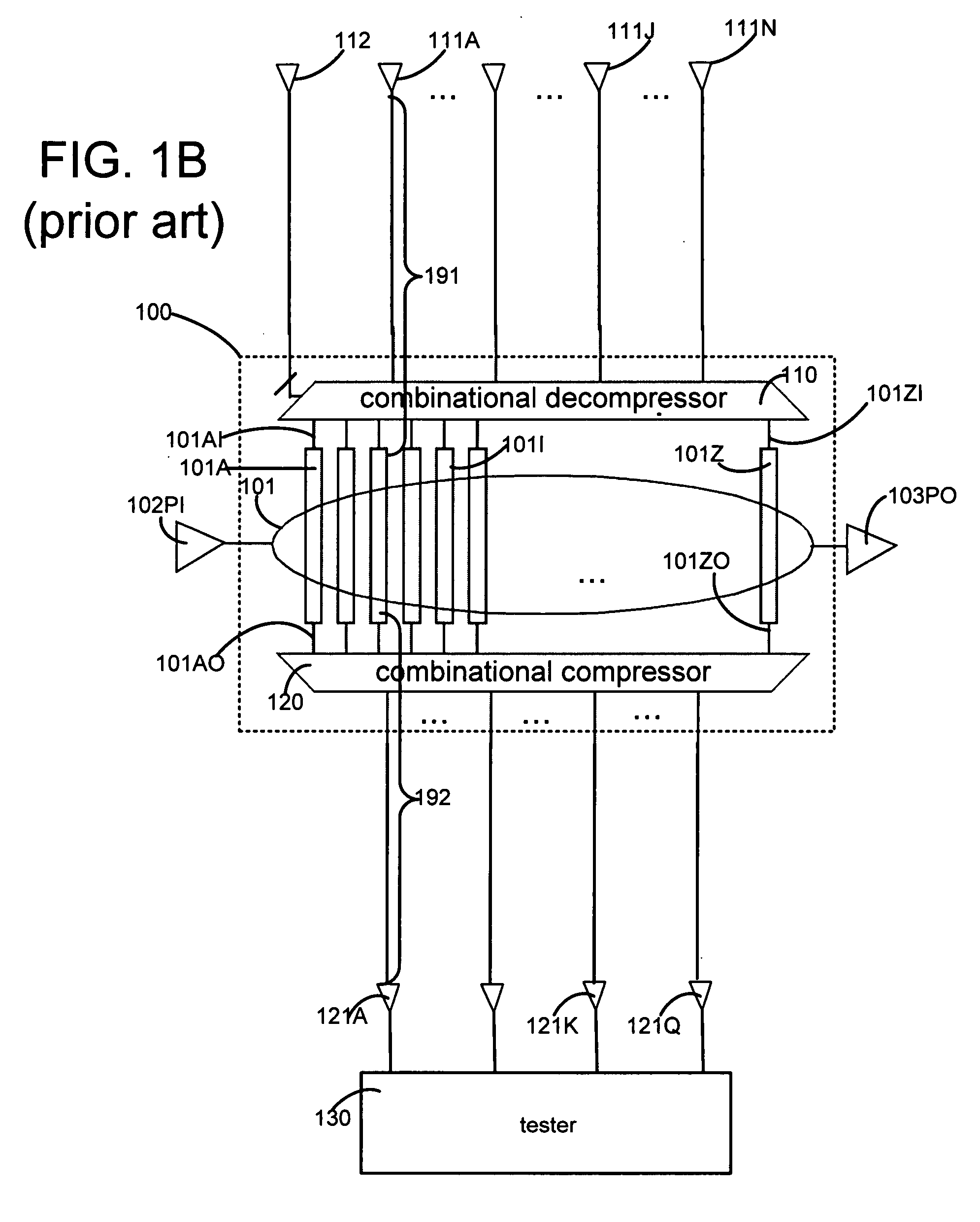
[0050]An electronic device in several embodiments of the invention includes a scan compression circuit 200 (FIG. 2A) having a selector 230 that is operable on a per-shift basis, in multiple modes. Scan-based circuit 200 also includes a compressor 220 which has several groups 221A-221Z of lines that are coupled to selector 230. Compressor 220 is architected in the normal manner, i.e. under an assumption that lines in each group carry the same data, namely data extracted from a respective one of scan chains 101A-101Z in the electronic device. Typically, each line within a group is connected internally within compressor 220 to a different block (e.g. implemented by an XOR gate) which combines data from lines of different groups. Hence, a compressor 220 which is used with selector 230 of some embodiments may be similar or identical to any compressor in the prior art, such as compressor 120 of FIG. 1D.

[0051]However, selector 230 does not supply identical signals to all lines within a gro...


PUM


Abstract

A scan-based circuit includes a selector that is implemented by multiple observation logics. Each observation logic is coupled to a scan chain to receive data to be supplied to a combinational compressor. Each observation logic is also coupled to a single input line in a corresponding group of input lines of the combinational compressor, to selectively supply data from the coupled scan chain. Each observation logic may be coupled to additional input lines (if present) in the corresponding group. The selector is operable on a per-shift basis in (a) transparent mode wherein data is supplied to all input lines and (b) several direct modes wherein data from only one scan chain is supplied at each compressor output without overlap.

Description

BACKGROUND[0001]1. Field of the Invention[0002]The invention relates to an architecture for a scan-based integrated circuit (IC). More specifically, the invention relates to a method and circuitry to perform scan compression using a selector operable on a per-shift basis, in multiple modes.[0003]2. Related Art[0004]Testing digital circuits accounts for a significant part of the cost to design, manufacture, and service electronic systems. Scan has long been the fundamental design-for-test (DFT) method to control test costs and aid silicon debug and fault diagnosis, but the number and size of scan test vectors is steadily increasing—even for highly compacted vector sets generated with modern automatic test pattern generation (ATPG).[0005]A scan test pattern is shown by flow 10 in FIG. 1A. In flow 10, step 11 sets up the scan chain configuration using flip-flops in the design, thereby identifying the scan cells of the scan chain. Step 12 shifts the scan-in values into the active scan c...

Claims


Application Information

Patent Timeline
Patent Type & Authority Applications(United States)
IPC IPC(8): H03K19/173G06F17/50
CPCG06F17/505G06F2217/14H03M7/30G06F30/327G06F30/333
Inventor WOHL, PETERWAICUKAUSKI, JOHN A.RAMNATH, SANJAYKAPUR, ROHITWILLIAMS, THOMAS W.
Owner SYNOPSYS INC
Why Eureka
Try Eureka