Wind energy plant tower

a technology for wind energy plants and towers, applied in wind energy generation, motors, mechanical equipment, etc., can solve the problems of ever-increasing problems affecting the operation of wind energy plants, the installation of towers, etc., and achieve the effect of simplifying the manufacture of wall sections, uniform connection, and significantly simplifying the production of wall sections

Inactive Publication Date: 2008-10-23
NORDEX ENERGY
View PDF9 Cites 43 Cited by
  • Summary
  • Abstract
  • Description
  • Claims
  • Application Information

AI Technical Summary

Benefits of technology

[0009]The wall sections form each one a separate structural component at a time and are connected to each other via the connection bores when the tower is installed. The wall sections are made of metal, preferably steel. The border sections with the connection bores define each at a time a surface which runs along the outer periphery of the tower wall or in a constant distance to it. Thus, the border sections are not realised as flanges which project out of the surface formed by the tower wall like in the state of the art. In particular, the border sections are not more offset against the centre sections than is preset by the desired outer periphery of the tower wall. Instead, the border sections form a uniform lateral continuation of the centre sections. Thus, the border sections run “parallel” to the outer periphery, i.e. they can run immediately along the periphery and form the same, or offset to the outer periphery. Through this, it is achieved that the border sections form an integral constituent part of the wall sections and the tower wall. Furthermore, the production of the wall sections is significantly simplified, because the wall sections do not have to be provided with a flange. Furthermore, the wall sections become more compact because there are no parts projecting out of the surface and through this, they can be transported more simply, as the case may be. The danger to damage a flange in the transportation is reduced.
[0026]According to a further embodiment, the border sections of a wall section extend across the whole length of the wall section in the longitudinal direction of the tower. In principle, the border sections can also be formed only sectionwise. However, the extension across the whole length of the wall sections simplifies the manufacture of the wall sections and results in a more uniform connection with higher staunchness between the neighbouring wall sections.

Problems solved by technology

With the increasing power capacity and magnitude of wind energy plants, the transportation and the installation of the towers impose ever-increasing problems for the wind energy plant operators.

Method used


Image

  • Wind energy plant tower
  • Wind energy plant tower
  • Wind energy plant tower

Examples


Embodiment Construction

[0034]While this invention may be embodied in many different forms, there are described in detail herein a specific preferred embodiment of the invention. This description is an exemplification of the principles of the invention and is not intended to limit the invention to the particular embodiment illustrated

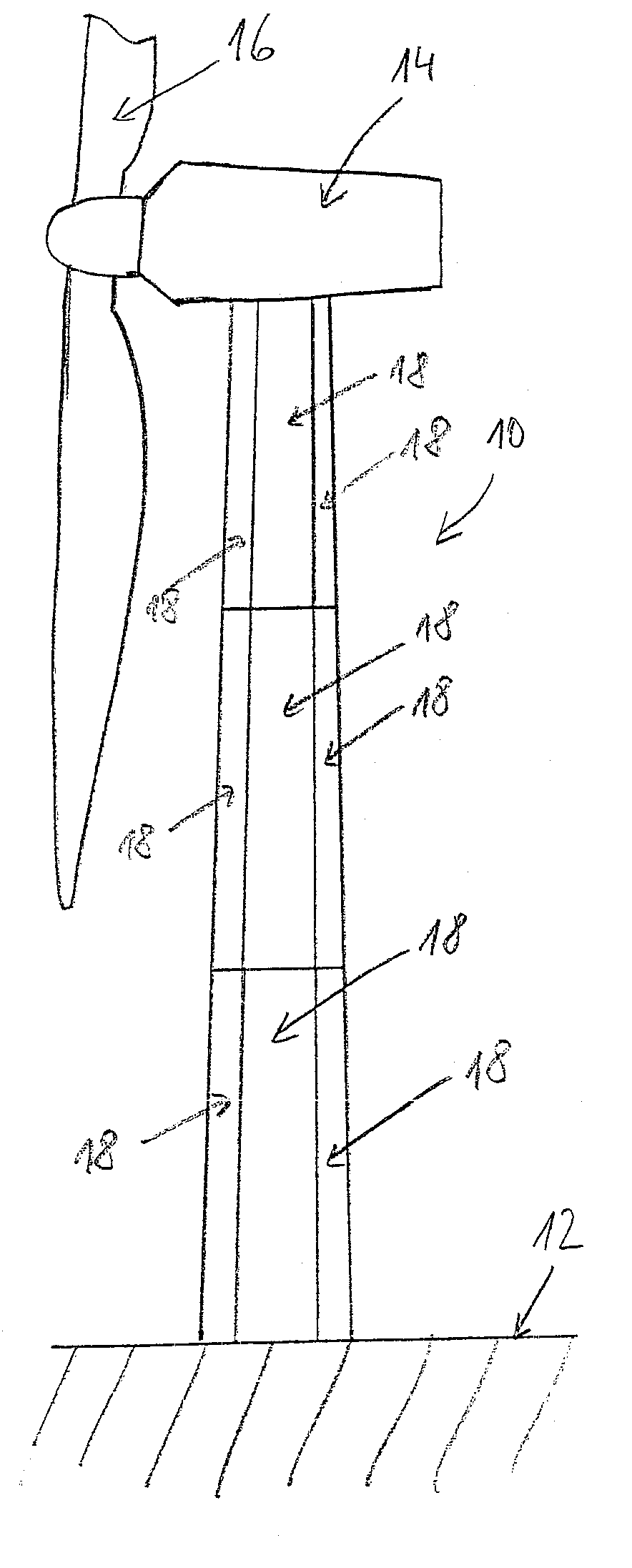
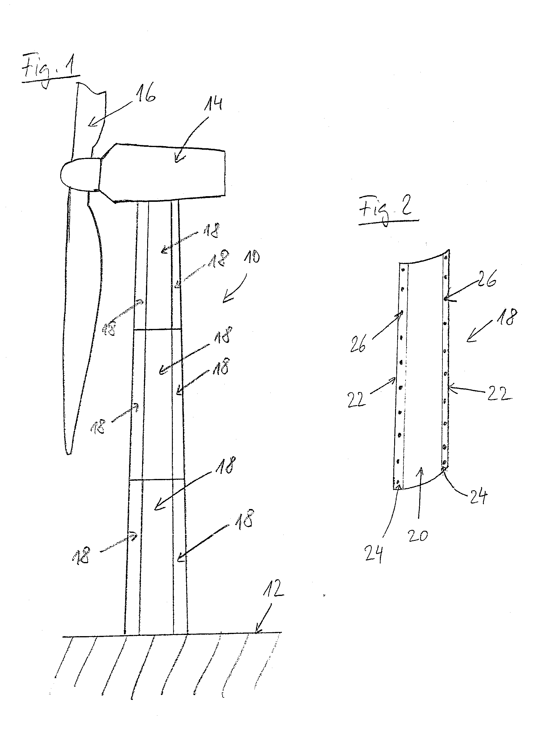
[0035]In the simplified depiction of FIG. 1, one recognizes a wind energy plant tower 10, which is anchored in a foundation 12 and carries a nacelle 14 of the wind energy plant. On the nacelle, the indicated rotor 16 of the wind energy plant is fastened. The tower 10 is composed of a plurality of wall sections 18. In the example, an equal number of wall sections 18 constitute one of three tower segments at a time, which are arranged on top of each other. In this, each wall section extends across the height of one tower segment in the vertical direction. Depending on the magnitude of the tower and other general conditions, a greater or a smaller number of tower segments can als...


PUM


Abstract

A wind energy plant tower with a load-bearing tower wall, which has a circulating outer periphery and consists of a plurality of wall sections, which each one have one centre section and two border sections running in the longitudinal direction of the tower, which are provided with a plurality of connection bores, wherein the surfaces defined by the border sections run along the outer periphery or in a constant distance to the same, and the connection bores are aligned transversely to the outer periphery.

Description

CROSS-REFERENCE TO RELATED APPLICATIONS[0001]Not applicable.STATEMENT REGARDING FEDERALLY SPONSORED RESEARCH[0002]Not applicable.BACKGROUND OF THE INVENTION[0003]The present invention is related to a wind energy plant tower with a load-bearing tower wall, which has a circulating outer periphery and consists of a plurality of wall sections, which each one have one centre section and two border sections running in the longitudinal direction of the tower, which are provided with a plurality of connection bores.[0004]With the increasing power capacity and magnitude of wind energy plants, the transportation and the installation of the towers impose ever-increasing problems for the wind energy plant operators. Even the cost for the production, the transportation and the installation of the towers come more and more into the focus of attention. In order to cope with this situation, towers for wind energy plants are known in the state of the art, which are subdivided into plural tower segme...

Claims


Application Information

Patent Timeline
Patent Type & Authority Applications(United States)
IPC IPC(8): E04H12/00
CPCE04H12/08F03D11/04F05B2240/912Y02E10/728F03D13/20Y02E10/72
Inventor FRANKE, MICHAEL
Owner NORDEX ENERGY
Why Eureka
Try Eureka