
Flexible Parallel Manipulator For Nano-, Meso- or Macro-Positioning With Multi-Degrees of Freedom

a parallel manipulator and multi-degree technology, applied in the direction of mechanical control devices, instruments, process and machine control, etc., can solve the problems of scaling laws of mechanical friction, fabrication, and difficult fabrication and control,

Inactive Publication Date: 2008-10-23
ZHU ZHENQI +2
View PDF9 Cites 34 Cited by
  • Summary
  • Abstract
  • Description
  • Claims
  • Application Information

AI Technical Summary

Problems solved by technology

Such designs have traditional mechanical rotary or translational joints that are difficult to fabricate and control due to friction.
The primary disadvantage of this design is adequate range of motion without mechanical interference or unacceptable bond strains.
Scaling laws in mechanical friction, backlash, and fabrication have also presented problems.
Therefore, the limited range of motion due to the flexure joint and an increased complexity in design, if a large range of motion is to be accumulated through repeated use of the flexure joints, are disadvantages of these designs.
The physical size of the positioning systems used in the microscopes compared with the three-dimensional nanoscale features of the specimen limits ‘full’ observation and ‘full freedom’ manipulation around the nanoscale features on a specimen.
Gordon and Breach Science Publishers, New York, N.Y.), and is still a problem as the probes and beams cannot be rotated locally around the three-dimensional features of a specimen with large angles of rotation (Postek (Sep. 8-12, 2004) Research Directions II Report—Grand Challenge Workshop on Instrumentation and Metrology, NIST).
Difficulties with these approaches include the limited degrees of freedom and range of motion.
3:1593), further miniaturization of these designs for in situ applications has proven difficult.
), MEMS-based designs are limited in their ability to deliver a large range of motion with full six degrees of freedom control.
Designs including the HexFlex™-based six-axis nano-manipulator (Culpepper and Anderson (2004) Prec. Eng. 28:469-482) have been suggested for use as microscale nanopositioners; however, the etched legs of these devices are brittle and provide a small range of motion.

Method used


Image

  • Flexible Parallel Manipulator For Nano-, Meso- or Macro-Positioning With Multi-Degrees of Freedom
  • Flexible Parallel Manipulator For Nano-, Meso- or Macro-Positioning With Multi-Degrees of Freedom
  • Flexible Parallel Manipulator For Nano-, Meso- or Macro-Positioning With Multi-Degrees of Freedom

Examples


Embodiment Construction

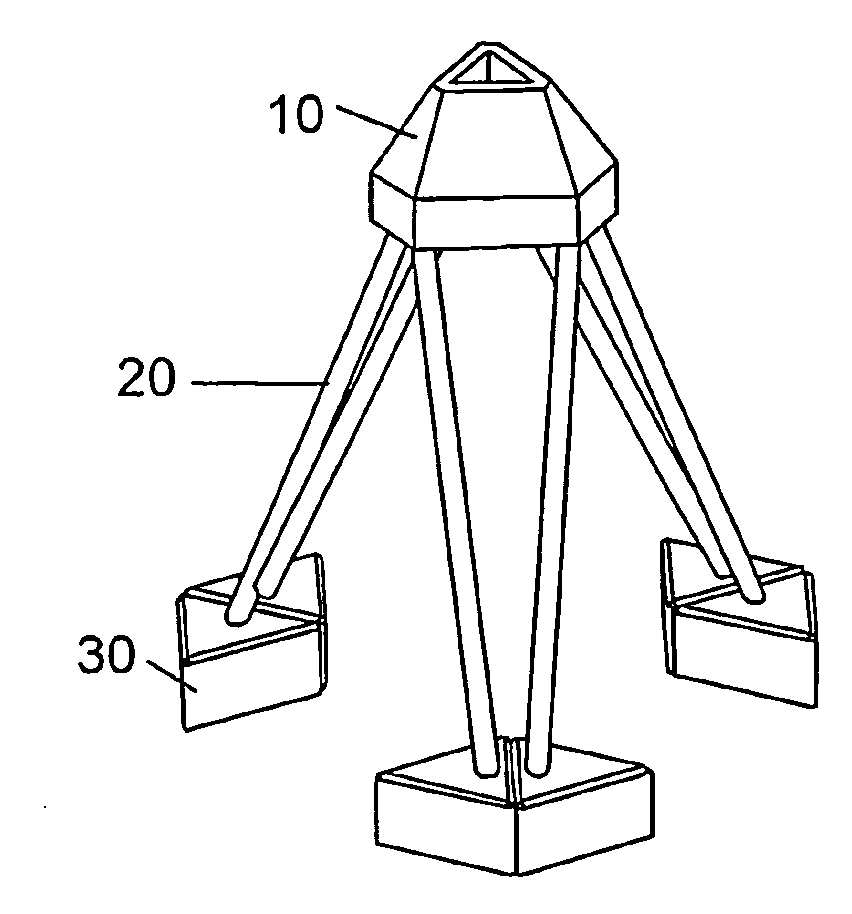
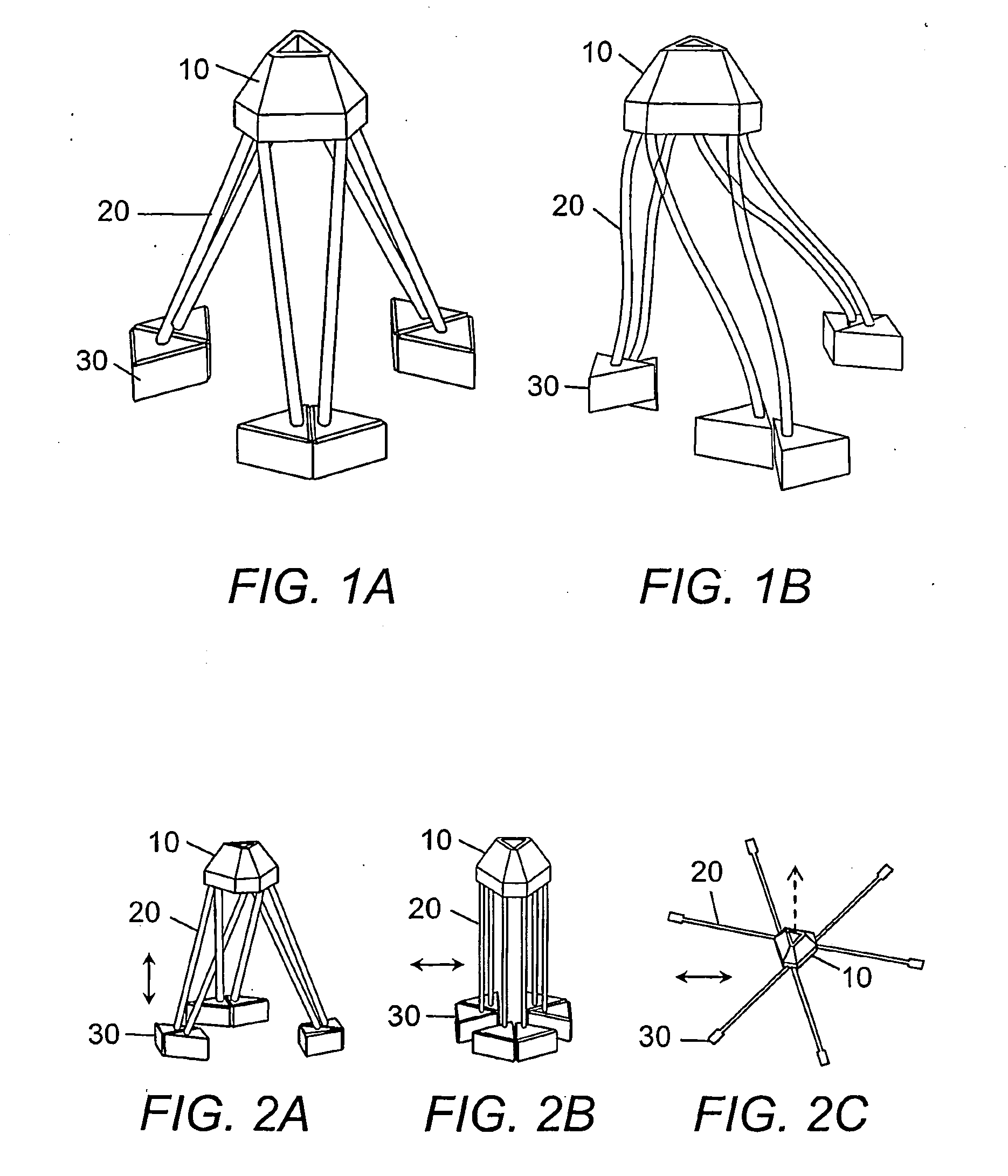
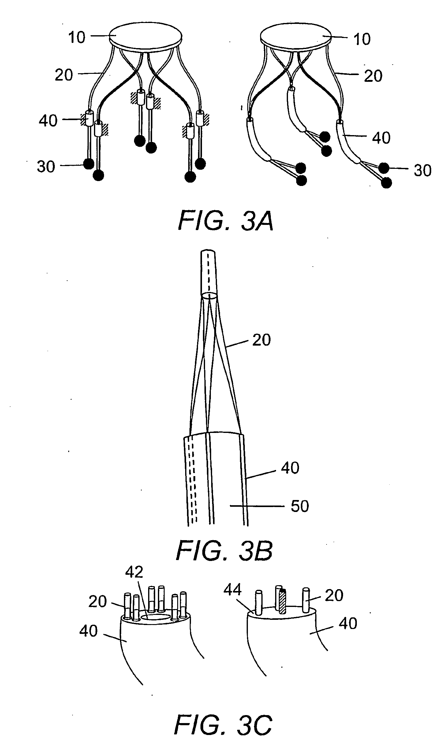
[0017]The present invention is a flexible parallel manipulator device based on the jointless motion mechanism commonly found in nature, e.g., cilia and flagella. The jointless manipulator disclosed herein is advantageously scalable and can be used for nano-, meso- or macro-manipulation as it provides friction- and backlash-free, multi-degrees of freedom motion. Referring to FIG. 1, the flexible parallel manipulator device is composed of a plurality of independent elastic fiber legs 20 which are attached, welded or bonded using standard joining methods (e.g., fusion welding, solid-state welding, brazing, soldering, adhesive bonding, and mechanical fastening or clamping) to a top platform 10 at various locations. In particular embodiments, the device has at least two elastic fiber legs, three elastic fiber legs, four elastic fiber legs, five elastic fiber legs, or more than six elastic fiber legs. In other embodiments, the device has at least six elastic fiber legs (see, e.g., FIG. 1)...


PUM


Abstract

The present invention is a friction- and backlash-fee flexible parallel manipulator device. The device is composed of multiple elastic fiber legs with various physical properties, a top platform, and a bottom platform. With multiple degrees of freedom, the motion of the top platform is controlled by the multiple elastic fiber legs whose lengths or curvatures between the top and bottom platforms are controlled based on the required motion of the top platform. The device can be used for nano-, micro-, or meso-manipulation.

Description

INTRODUCTION[0001]This application claims benefit of U.S. Provisional Patent Application Ser. No. 60 / 667,794, filed Apr. 1, 2005, the contents of which are incorporated herein by reference in their entirety.BACKGROUND OF THE INVENTION[0002]Nanoscale-sized manipulator designs having large ranges of motions in all six degrees of freedom include a Stewart platform (Drexler (1992) Nanosystems: Molecular Machinery, Manufacturing, and Computation. John Wiley & Sons, Inc., New York, N.Y.), a serial robot with mechanical bearings (Drexler (1992) supra), a double tripod (Merkle (1997) Nanotechnology 8:47) and a modified Stewart platform with eight cranks (Drexler, et al., world-wide web imm.org / Parts / Parts2 with the extension html). Such designs have traditional mechanical rotary or translational joints that are difficult to fabricate and control due to friction. The modified Stewart platform (Freitas (1999) Nanomedicine, Volume I: Basic Capabilities. Landes Bioscience, Austin, Tex.) is a 2,...

Claims


Application Information

Patent Timeline
Patent Type & Authority Applications(United States)
IPC IPC(8): B25J17/00B25J18/06G06F17/00
CPCB25J7/00Y10T74/20348B25J17/0266
Inventor ZHU, ZHENQICUI, HONGLIANGPOCHIRAJU, KISHORE
Owner ZHU ZHENQI
Learn More