Acoustic attenuation chamber

a technology of attenuation chamber and acoustic energy, which is applied in the field of passive silencer, can solve the problems of increasing resonator loss, and achieve the effects of reducing the velocity of flow passing, reducing noise of air movement, and increasing broadband attenuation of acoustic energy

Inactive Publication Date: 2008-10-23
VIASYS SLEEP SYST
View PDF10 Cites 75 Cited by
  • Summary
  • Abstract
  • Description
  • Claims
  • Application Information

AI Technical Summary

Benefits of technology

[0017]The motor blower unit may also be suspended in the blower chamber by means of a plurality of suspension mounts extending laterally outwardly from a blower housing. In this manner, the suspension mounts act as vibration isolators preventing mechanical vibration and air movement vibration from propagating to the housing assembly. The blower chamber may further include a perforated plate resonator backed by dissipative elements (e.g., porous material such as open-cell foam) to further attenuate air movement noise. The chamber walls of the inlet chamber, acoustic chamber and blower chamber may further include a plurality of randomly-placed thick sections which are specifically configured to prevent vibration of the chamber wall at a single low frequency resonance. The locally thick sections instead induce multiple higher-frequency resonances of lower amplitude in the chamber walls.
[0018]The flow path along the inlet chamber, a

Problems solved by technology

In this manner, the perforated plates produce a grazing flow

Method used


Image

  • Acoustic attenuation chamber
  • Acoustic attenuation chamber
  • Acoustic attenuation chamber

Examples


Embodiment Construction

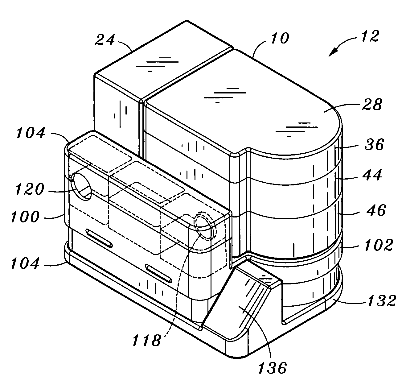
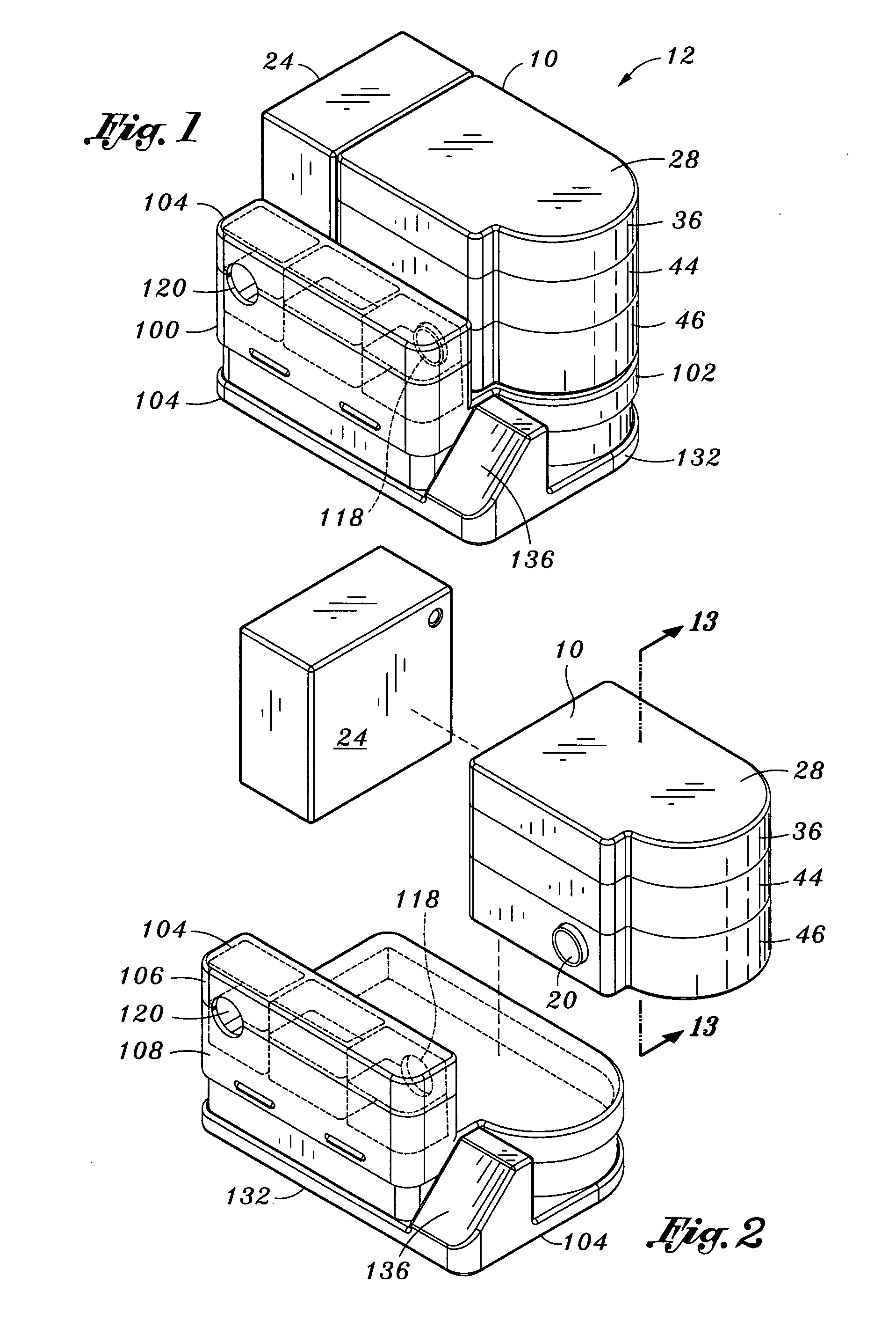
[0045]Referring now to the drawings wherein the showings are for purposes of illustrating preferred embodiments of the present invention and not for purposes of limiting the same, shown is a passive silencer 10 adapted for use with a blower device 12. In one embodiment, the blower device 12 is configured as a continuous positive airway pressure (CPAP) device although the passive silencer 10 may be used in a variety of other ventilation systems. Exemplary uses of the passive silencer 10 include a bedside or tabletop-mounted blower device as disclosed in commonly-owned U.S. Pat. No. 7,195,014 entitled “Portable Continuous Positive Airway Pressure System”, the entire contents of which is incorporated by reference herein. However, the passive silencer 10 may also be used in portable or wearable versions of the CPAP device.

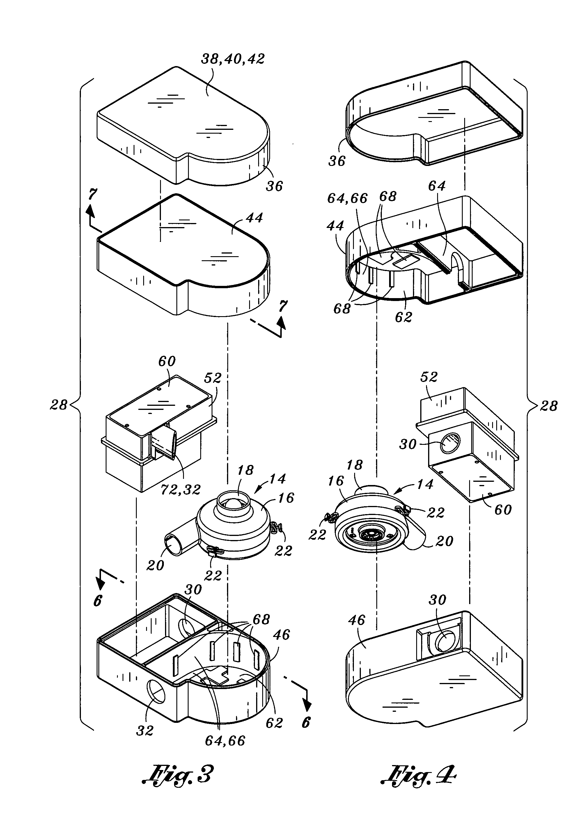
[0046]The passive silencer 10 may be implemented in several embodiments of which two are illustrated in FIGS. 1-23. More specifically, FIGS. 1-14 illustrate the integr...


PUM


Abstract

A silencer for a CPAP device comprises a housing assembly defining a flow path passing therethrough and including at least one of an inlet chamber, an acoustic chamber and a blower chamber. Each of the chambers has an inlet and an outlet for fluid communication therebetween. The silencer includes a combination of reactive components, resonators and dissipative elements disposed within the inlet, acoustic and blower chambers. The reactive component may be configured as a compliant-walled reactive tube. The resonator may be configured as a perforated plate defining a cavity volume. The dissipative element may comprise porous material substantially occupying the cavity volume bounded by the perforated plate in the chamber walls.

Description

CROSS-REFERENCE TO RELATED APPLICATIONS[0001]The present application is related to commonly-owned U.S. Pat. No. 7,195,014 entitled PORTABLE CONTINUOUS POSITIVE AIRWAY PRESSURE SYSTEM filed on May 13, 2005, and to commonly-owned U.S. Utility patent application Ser. No. 11 / 649,674 entitled USER INTERFACE AND HEAD GEAR FOR A CONTINUOUS POSITIVE AIRWAY PRESSURE DEVICE filed on Jan. 4, 2007, and commonly-owned U.S. Utility patent application Ser. No. (unknown) entitled CONTINUOUS POSITIVE AIRWAY PRESSURE DEVICE AND CONFIGURATION FOR EMPLOYING SAME, filed on Apr. 17, 2007, the entire contents of each patent and application being incorporated by reference herein.STATEMENT RE: FEDERALLY SPONSORED RESEARCH / DEVELOPMENT[0002](Not Applicable)BACKGROUND[0003]The present invention relates generally to patient ventilation systems and, more particularly, to a passive silencer as may be used with a blower assembly for a continuous positive airway pressure (CPAP) device. The passive silencer is speci...

Claims


Application Information

Patent Timeline
IPC IPC(8): A61M16/16
CPCA61M16/0066A61M16/1075A61M16/16A61M2205/42A61M2205/502A61M16/109A61M16/024
Inventor LATHROP, RAYMONDHOFFMAN, LESLIE
Owner VIASYS SLEEP SYST
Why Eureka
Try Eureka