
Non-Metallic Flow-Through Electrodeless Conductivity Sensor and Leak Detector

a conductivity sensor and electrodeless technology, applied in the field of conductivity sensors, can solve the problems of not being able or desirable to immerse a sensor in the fluid, chemical attack or contamination of the solution and/or electrodes, and not being able or desirabl

Active Publication Date: 2008-10-23
SCHNEIDER ELECTRIC SYST USA INC
View PDF44 Cites 57 Cited by
  • Summary
  • Abstract
  • Description
  • Claims
  • Application Information

AI Technical Summary

Benefits of technology

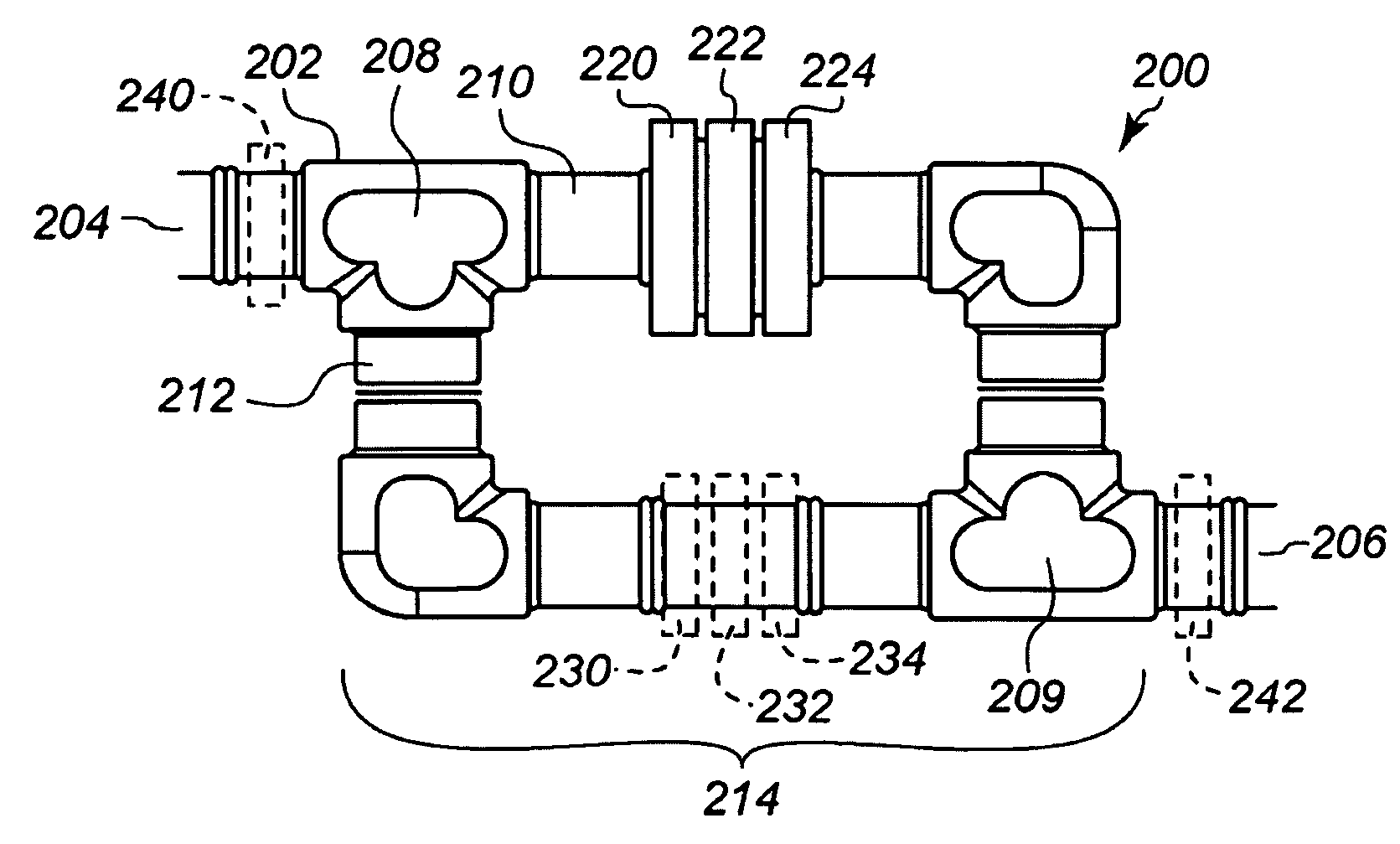
This configuration allows for accurate conductivity measurements of fluids incompatible with metals, enhancing sensitivity by compensating for the adverse effects of high fluid-loop resistance and preventing chemical contamination.

Problems solved by technology

This technique, however, is not optimal if the solution to be measured is chemically incompatible with the metallic electrodes, e.g., resulting in chemical attack or contamination of the solution and / or electrodes.
Where a fluid to be measured is flowing through a conduit, it may not be possible or desirable to immerse a sensor in the fluid.
A drawback of this approach, however, is that metallic pipe portions cannot be used when the process fluid attacks or is otherwise incompatible with metals.
A drawback of this approach is that the limited cross section, relatively long length and high resistance of the fluid itself, adds a net resistance to the induced current which tends to adversely affect the sensitivity of conductivity measurement.
A drawback to this approach is that Ogawa's toroids are taught to be coplanar and physically separated in order to reduce leakage coupling between the transformers.

Method used


Image

  • Non-Metallic Flow-Through Electrodeless Conductivity Sensor and Leak Detector
  • Non-Metallic Flow-Through Electrodeless Conductivity Sensor and Leak Detector
  • Non-Metallic Flow-Through Electrodeless Conductivity Sensor and Leak Detector

Examples


Embodiment Construction

[0022]In the following detailed description, reference is made to the accompanying drawings that form a part hereof, and in which is shown by way of illustration, specific embodiments in which the invention may be practiced. These embodiments are described in sufficient detail to enable those skilled in the art to practice the invention, and it is to be understood that other embodiments may be utilized. It is also to be understood that structural, procedural and system changes may be made without departing from the spirit and scope of the present invention. The following detailed description is, therefore, not to be taken in a limiting sense, and the scope of the present invention is defined by the appended claims and their equivalents. For clarity of exposition, like features shown in the accompanying drawings are indicated with like reference numerals and similar features as shown in alternate embodiments in the drawings are indicated with similar reference numerals. Where used in...


PUM

PropertyMeasurementUnit
electric currentaaaaaaaaaa
conductivityaaaaaaaaaa
voltageaaaaaaaaaa

Abstract

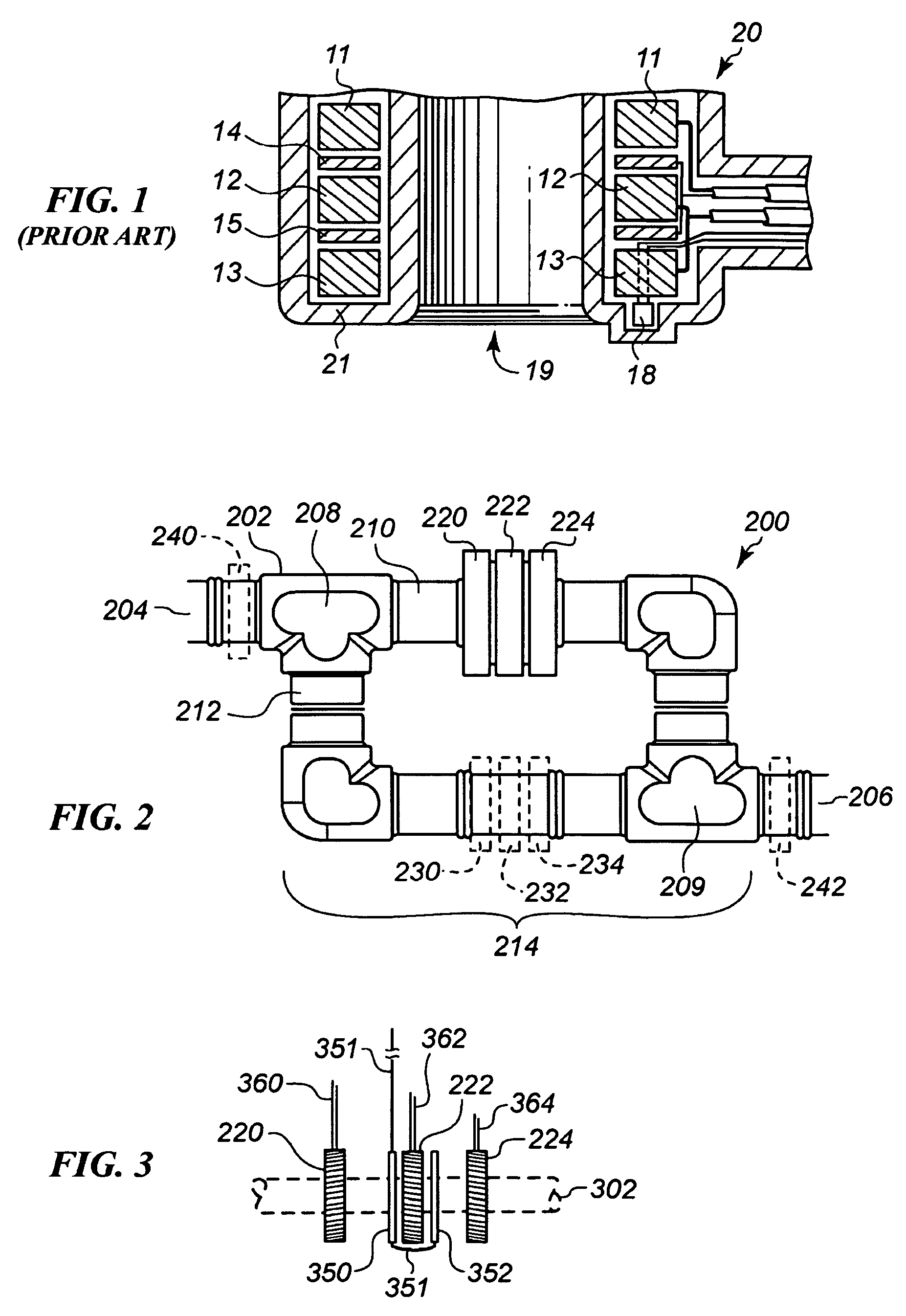
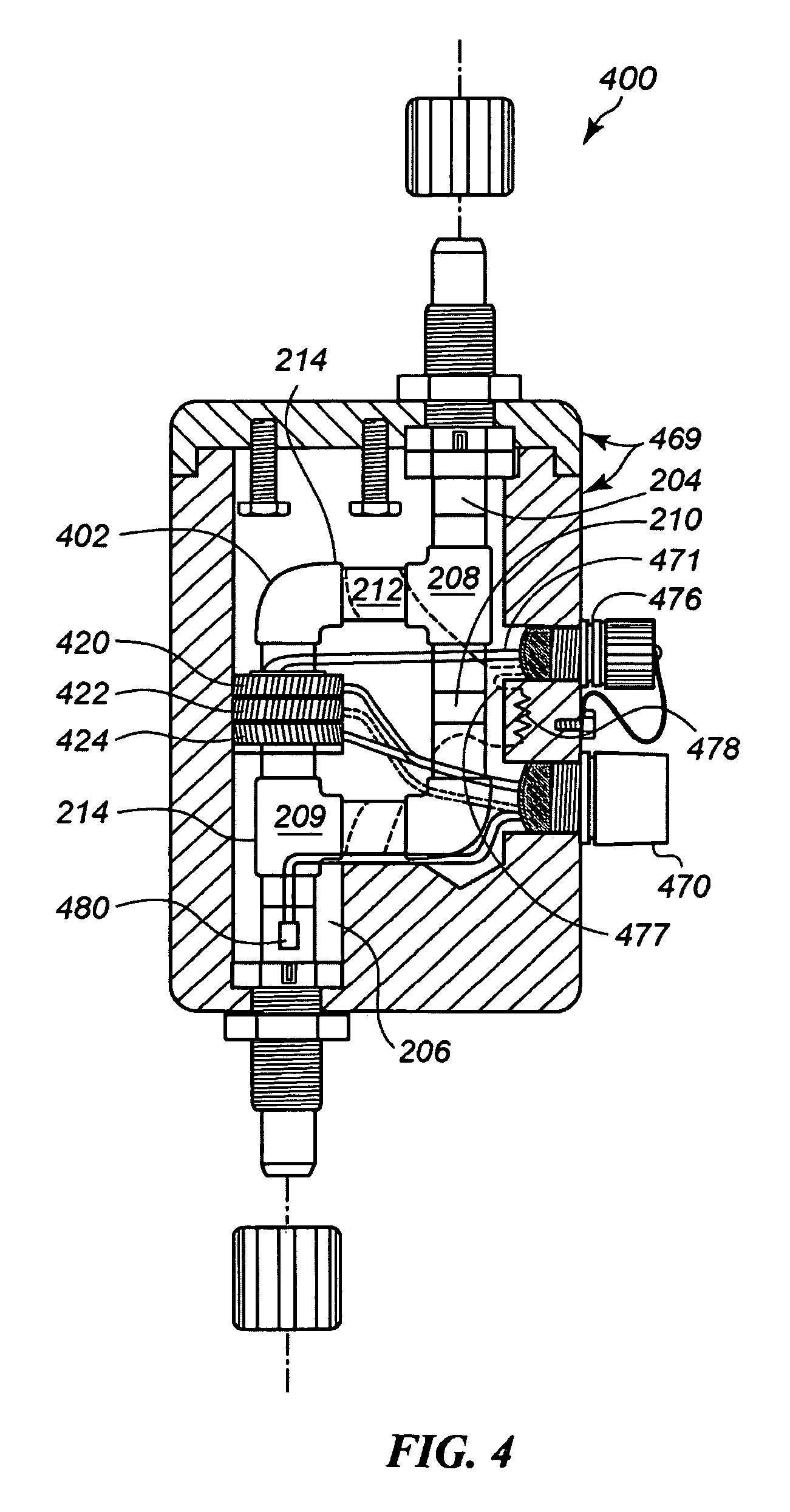
A non metallic flow through electrodeless conductivity sensor is provided with a conduit having primary and secondary process fluid flowpaths to form a fluid loop. At least one drive and one sense toroid surround the conduit on the fluid loop. Voltage supplied to the drive toroid induces a current in the sense toroid via the fluid loop to eliminate any need for metallic electrodes in contact with the process fluid. At least one additional drive and / or sense toroid is disposed on the fluid loop to enhance induction. Optionally one or more sense coils are disposed about the conduit outside of the fluid loop to cancel out stray electrical noise. An optional conductor disposed along the conduit detects any fluid leakage through changes in resistance thereof.

Description

RELATED APPLICATION [0001]This application is a divisional of U.S. patent application Ser. No. 11 / 351,856 entitled Non-Metallic Flow-Through Electrodeless Conductivity Sensor and Leak Detector, filed on Feb. 9, 2006 which claims priority to U.S. Provisional Patent Application Ser. No. 60 / 676,765 entitled Non-Metallic Flow Through Electrodeless Conductivity Sensor, filed on May 2, 2005.TECHNICAL FIELD [0002]This invention relates to conductivity sensors and more particularly to electrodeless conductivity sensors configured to detect the conductivity of process fluid flowing through a conduit.BACKGROUND INFORMATION [0003]Throughout this application, various publications, patents and published patent applications are referred to by an identifying citation. The disclosures of the publications, patents and published patent applications referenced in this application are hereby incorporated by reference into the present disclosure.[0004]Conductivity measurements of a chemical solution may...

Claims


Application Information

Patent Timeline
Patent Type & Authority Applications(United States)
IPC IPC(8): G01N27/02G01R3/00
CPCY10T29/49002G01N27/023
Inventor QUACKENBUSH, JOHN KEVINBOWER, MICHAEL M.TALUTIS, STEPHEN B.MCKINLAY, DONALD S.
Owner SCHNEIDER ELECTRIC SYST USA INC
Learn More