Cross-coupled vertebral stabilizers incorporating spinal motion restriction

a vertebral stabilizer and cross-coupling technology, applied in the field of orthopaedic spinal surgery, can solve the problems of increasing tension, reducing pressure on spinal nerves, and increasing distraction,

Inactive Publication Date: 2008-10-23
FERREE BRET A
View PDF8 Cites 31 Cited by
  • Summary
  • Abstract
  • Description
  • Claims
  • Application Information

AI Technical Summary

Benefits of technology

[0016]In the case of vertebral alignment, the lower screw portion is preferably a pedicle screw, and the mechanism includes a first body having an interrupted side wall with an inner surface, and a second body having a rotatable cam. In this case, the mechanism facilitates a first state, wherein the relationship between the cam and the inner surface of the side wall is such that the cables pass therethrough, and a second state, wherein the cam is turned so as to retain the one or more cables against the inner wall of the side wall.
[0018]Initially, the pedicle screws were connected by fibrous bands to limit flexion of the spine (distraction of the posterior portion of the vertebrae). The devices were improved by covering the fibrous bands with rubber sleeves which help dampen the forces on the facets that occurs with spinal extension. That is, the rubber sleeves help prevent extension of the spine. Forces on the facets increase with extension.
[0022]Although the configuration may be used as an adjunct to spinal fusion, it may also be used to dampen motion as an adjunct to vertebral anthroplasty.

Problems solved by technology

First, it can decrease pressure on spinal nerves by increasing the size of the intervertebral foramen.
Second, distraction increases tension on the annulus fibrosis which, in turn, increases the stability of the vertebra-cage-vertebra construct.
Presumably the annular tension decreases with time, thus weakening the construct.
Furthermore, the annulus is weakened in many patients with severe degenerative disc disease.
As might be expected, the second surgery increases patient morbidity, insurance costs, and delays return to work.
Previous metal devices placed under the aorta have lead to aneurysms in some cases (Dunn Device).
Unfortunately, a few patients have died from rupture of the aneurysms.
Lateral fixation is not ideal with interbody cages.
First, lateral fixation cannot be used at the L5-S1 level.
Second, the vascular anatomy of many patients does not permit lateral fixation at the L4-L5 level.
Lateral instrumentation is difficult if not impossible in most patients in the supine position.
None use diagonal members to enhance compression and resist lateral movement, however.

Method used


Image

  • Cross-coupled vertebral stabilizers incorporating spinal motion restriction
  • Cross-coupled vertebral stabilizers incorporating spinal motion restriction
  • Cross-coupled vertebral stabilizers incorporating spinal motion restriction

Examples


Embodiment Construction

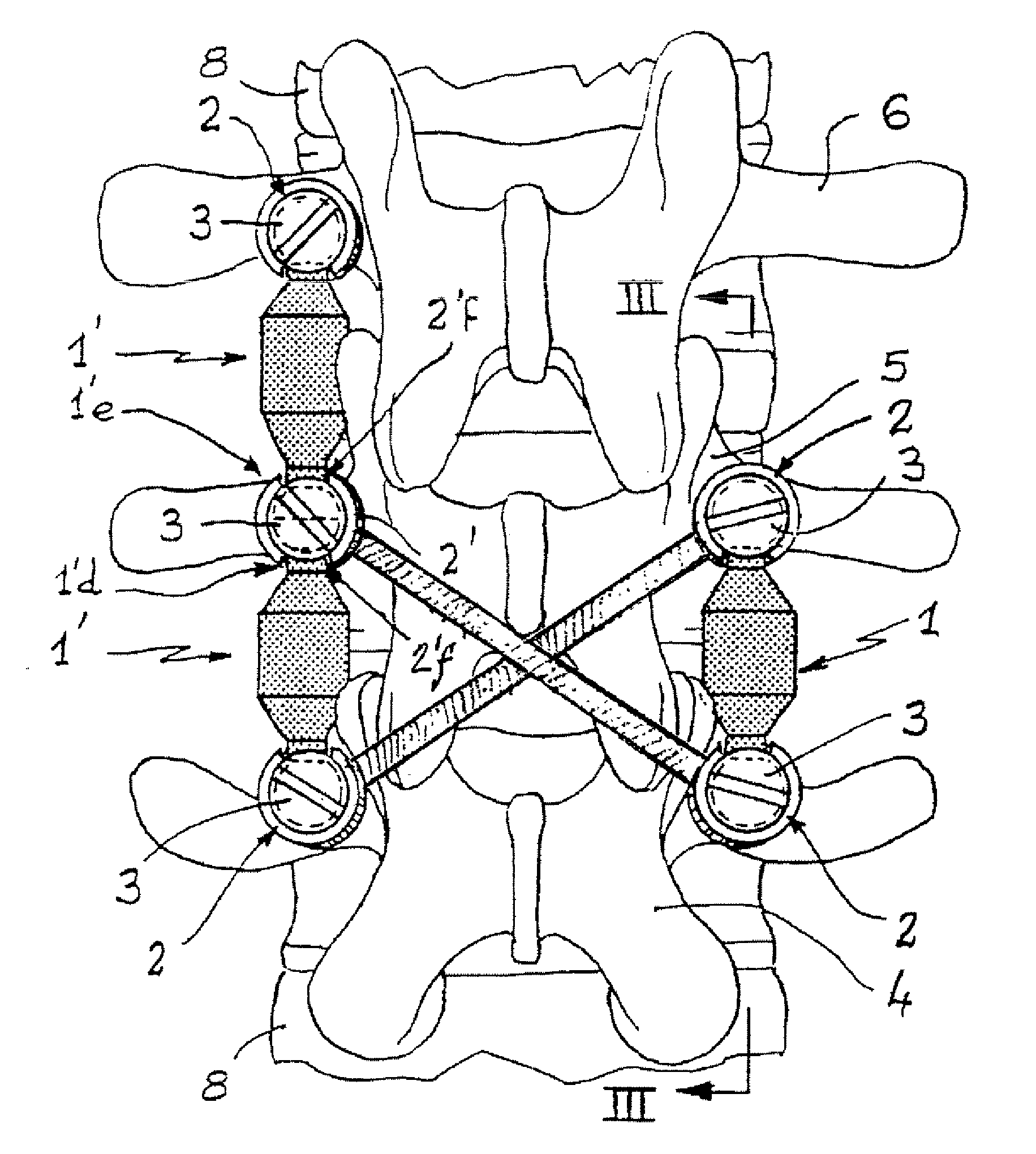
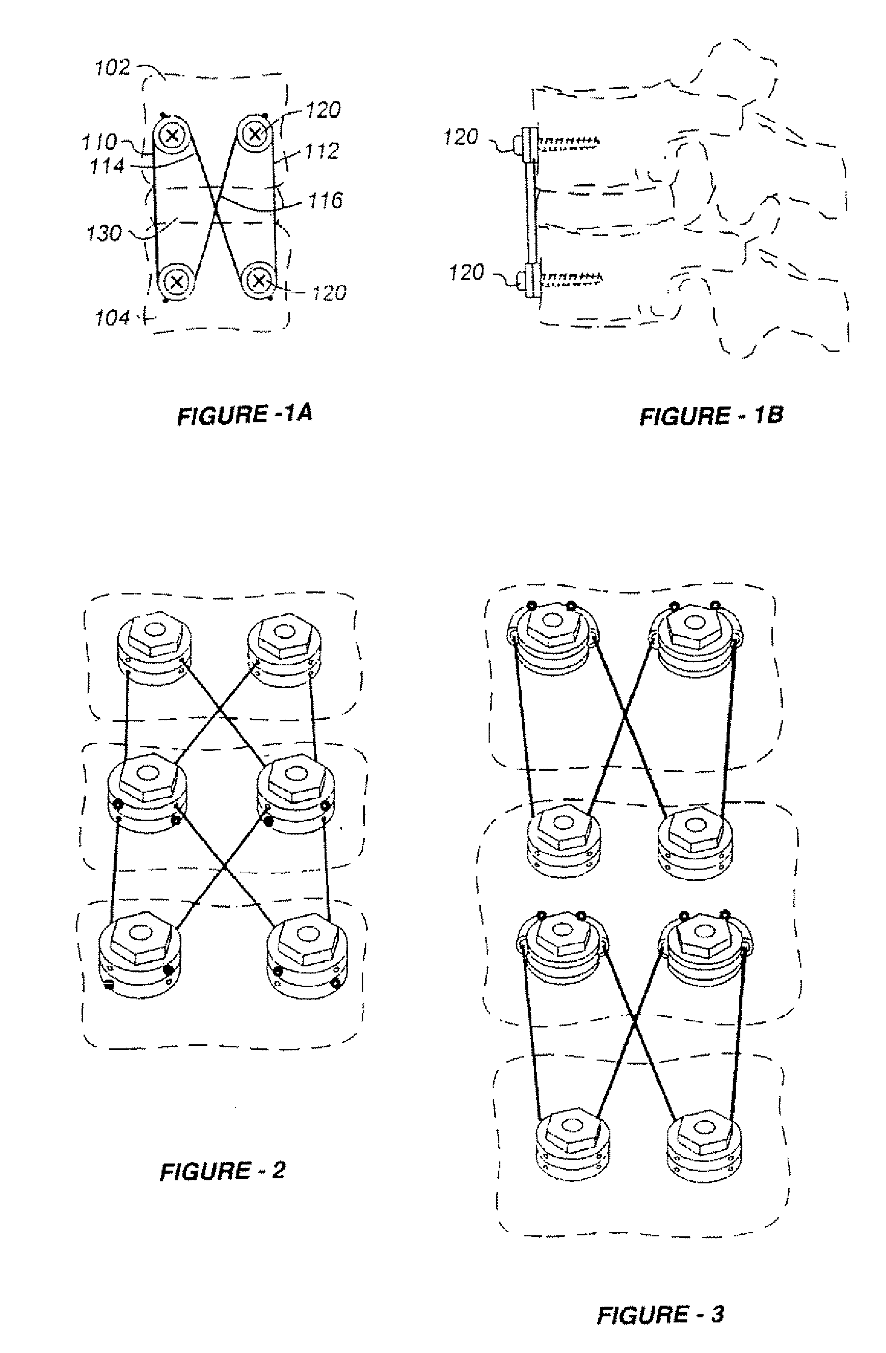
[0054]FIG. 1A is an anterior view of a cable-based cross-coupled vertebral stabilizing mechanism disclosed in U.S. Pat. No. 6,248,106, incorporated herein by reference. FIG. 1B is a drawing which shows the mechanism of FIG. 1A from a lateral perspective. In this illustration, the mechanism is used to join upper and lower vertebrae 102 and 104, respectively, though the mechanism is applicable to multiple levels, as shown in FIGS. 2 and 3. Note that some form of intervertebral cage and / or bone graft 130 may be used in between the vertebrae 102 and 104 to resist compression.

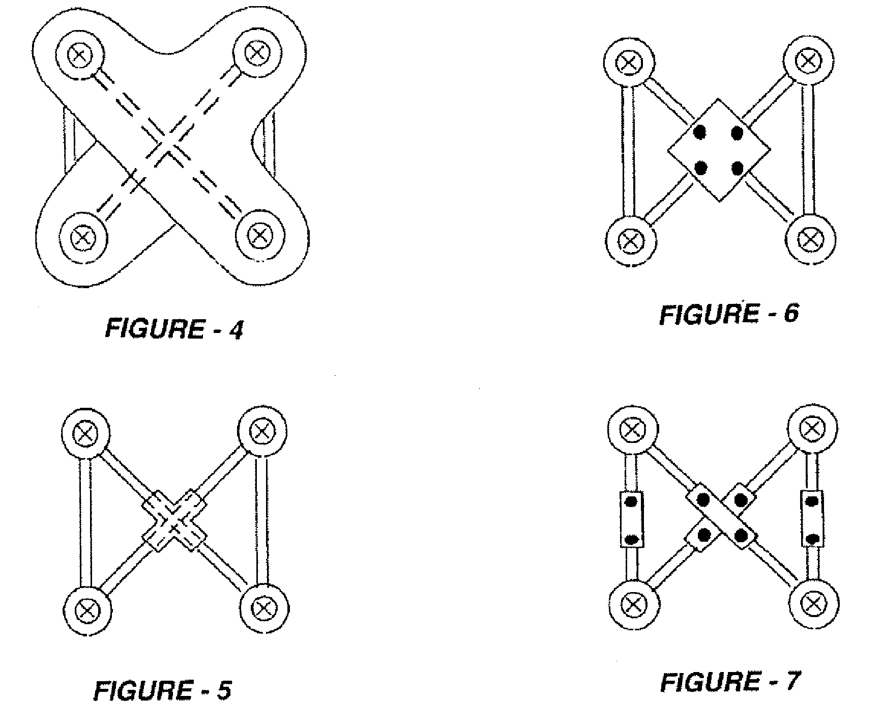
[0055]Broadly, the mechanism utilizes a pair of fasteners on each vertebrae, and elongated elements, preferably cables, in an axial and criss-crossed pattern to provide an arrangement that resists extension, lateral bending, and torsional / rotational stresses. As best seen in FIG. 1A, a preferred configuration utilizes a pair of screws 120 in the upper vertebrae, and a corresponding pair in the lower vertebrae, along...


PUM


Abstract

Methods for stabilizing upper and lower spinal vertebrae having a disc situated between the upper and lower vertebrae are described. First and second fasteners are inserted into the upper vertebra. Third and fourth fasteners are inserted into the lower vertebra. At least two of the first, second, third, and fourth fasteners are connected with an elongate element. In an alternative embodiment, at least three of the first, second, third, and fourth fasteners are connected with the elongate element. The elongate element may be an elastic connector or a cable. The elongate element may also have first and second ends that are connected by a crimp.

Description

REFERENCE TO RELATED APPLICATION[0001]This application is a continuation of U.S. patent application Ser. No. 10 / 152,485, filed May 21, 2002, which is a continuation-in-part of U.S. patent application Ser. No. 09 / 841,324, filed Apr. 24, 2001, which is a continuation-in-part of U.S. patent application Ser. No. 09 / 513,127, filed Feb. 25, 2000, now U.S. Pat. No. 6,248,106, the entire content of each application being incorporated herein by reference.FIELD OF THE INVENTION[0002]This invention relates generally to orthopedic spinal surgery and, in particular, to vertebral fixation methods and apparatus which provide multi-dimensional stability and apply compressive forces to enhance fusion.BACKGROUND OF THE INVENTION[0003]In surgeries involving spinal fixation, interbody cages are often used to restore disc space height, serve as a conduit for bone graft, and to help immobilize vertebrae undergoing fusion. Distracting the disc space prior to cage insertion restore disc space height. Distr...

Claims


Application Information

Patent Timeline
Patent Type & Authority Applications(United States)
IPC IPC(8): A61B17/70A61B17/04A61B17/00A61B17/84
CPCA61B17/70A61B17/7002A61B17/7005A61B17/7007A61B2017/7073A61B17/7031A61B17/705A61B17/7058A61B17/842A61B17/7022
Inventor FERREE, BRET A.
Owner FERREE BRET A
Why Eureka
Try Eureka