Method and apparatus to optimize engine warm up

Inactive Publication Date: 2008-10-23
GM GLOBAL TECH OPERATIONS LLC
View PDF3 Cites 150 Cited by
  • Summary
  • Abstract
  • Description
  • Claims
  • Application Information

AI Technical Summary

Benefits of technology

[0005]In accordance with an embodiment of the invention, a method and an article of manufacture are provided comprising a storage medium having machine-executable code stored therein effective to minimize energy loss of an internal combustion engine during engine warm-up. This includes code to monitor engine oper

Problems solved by technology

These systems consume substantial amounts of computer memory and a

Method used


Image

  • Method and apparatus to optimize engine warm up
  • Method and apparatus to optimize engine warm up
  • Method and apparatus to optimize engine warm up

Examples


Embodiment Construction

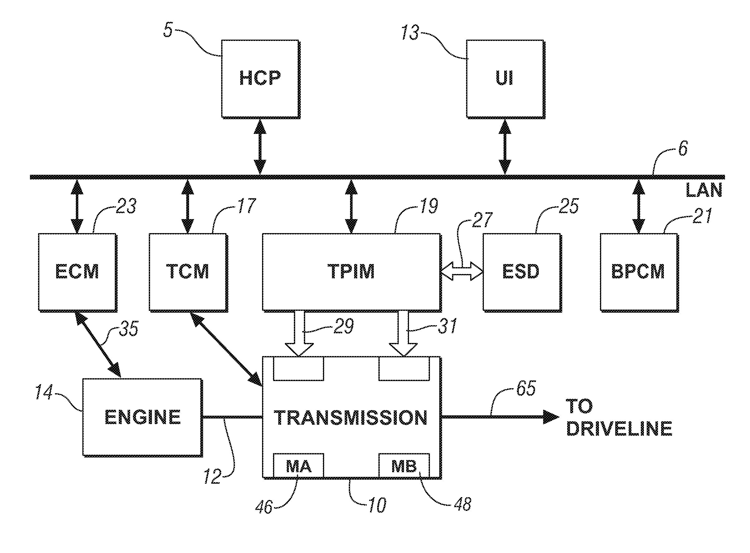
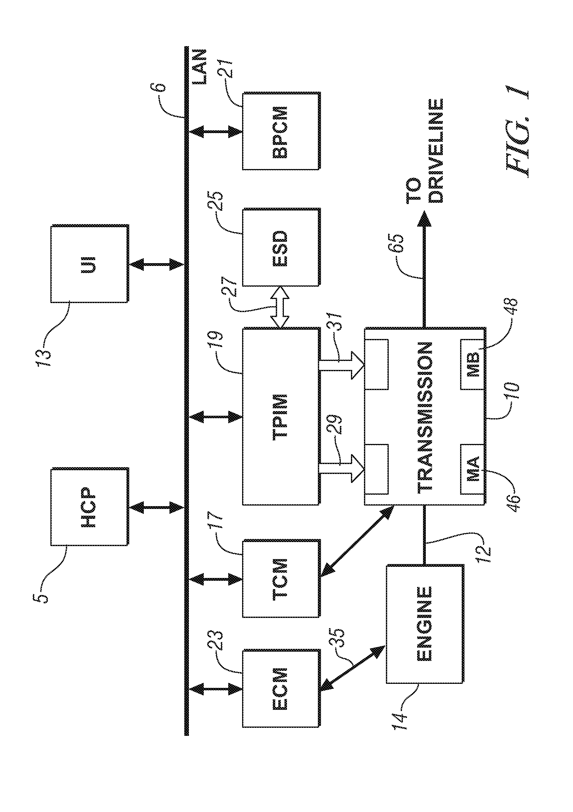
[0011]Referring now to the drawings, wherein the showings are for the purpose of illustrating the invention only and not for the purpose of limiting the same,FIG. 1 depicts a schematic diagram of a powertrain and control system illustrative of the invention. The elements described hereinafter provide coordinated control of the powertrain system. The powertrain comprises an internal combustion engine 14 and an electromechanical transmission 10 operative to provide a torque output to a driveline via an output shaft 65. The electromechanical transmission 10 includes a pair of electrical machines MA, MB 46, 48. The engine, transmission, and electrical machines are operative to transmit torque therebetween according predetermined control schemes and parameters not discussed in detail herein.

[0012]The exemplary internal combustion engine 14 comprises a multi-cylinder internal combustion engine selectively operative to transmit torque to the transmission via shaft 12, and can be either a s...


PUM


Abstract

There is provided a method and an apparatus to minimize energy loss of an internal combustion engine during engine warm-up. This includes monitoring engine operating conditions, and estimating a future energy loss. A power loss and a rate of change in the estimated future energy loss are determined. An engine control scheme effective to minimize the power loss and the rate of change in the estimated future energy loss is executed during the engine warm-up.

Description

TECHNICAL FIELD[0001]This invention pertains generally to control systems for powertrain systems.BACKGROUND OF THE INVENTION[0002]Powertrain control systems, including hybrid powertrain architectures, operate to meet operator demands for performance, e.g., torque and acceleration, which are balanced against other operator requirements and regulations, e.g., fuel economy and emissions. In order to optimize operation of the powertrain, there is a need to quantify engine power losses associated with operating conditions during ongoing operation.[0003]Prior art systems to determine instantaneous engine power losses have relied upon pre-calibrated tables stored in an on-board computer to determine losses. These systems consume substantial amounts of computer memory and are often unable to accommodate variations in operating conditions. The memory space is further compounded when other engine operating modes, e.g., cylinder deactivation, are introduced.[0004]There is a need to minimize ov...

Claims


Application Information

Patent Timeline
IPC IPC(8): F02D28/00F02N19/10
CPCF02D41/068F02D41/1406F02D2200/1006F02D2250/18
Inventor HEAP, ANTHONY H.LAHTI, JOHN L.
Owner GM GLOBAL TECH OPERATIONS LLC
Why Eureka
Try Eureka