
3c frame manufacturing method

a manufacturing method and frame technology, applied in the direction of adhesive processes with adhesive heating, adhesives, etc., can solve the problems of extreme material waste and failure, and achieve the effects of preventing defects including deformation, high bonding tenacity, and high shear strength

Inactive Publication Date: 2008-10-30
CHENG FWA INDAL +1
View PDF3 Cites 6 Cited by
  • Summary
  • Abstract
  • Description
  • Claims
  • Application Information

AI Technical Summary

Benefits of technology

[0013]The primary purpose of the present invention is to provide a manufacturing method for a 3C frame that allows cost reduction, automated production, and reduced reliance upon labor force.
[0014]The secondary purpose of the present invention is to provide a manufacturing method for a 3C frame that saves material costs by overcoming the problem of material waste found with the prior art when the core of the material must be removed in the punching process.
[0015]The thirdly purpose of the present invention is to provide a manufacturing method for a 3C frame that is environment friendly so to minimize hazards to human body, environment or work safety issues.

Problems solved by technology

1. Extreme waste of material to fail economic benefits since the entire sheet of material is punched while removing or hollowing the central portion.
2. The following disadvantages since the welding job is provided after multiple side frames are punched into shape:a. The welding job is only made possible for the same type of metal;b. Surface treatment of the frame can be done after the completion of the welding job since the welding job becomes very difficult and results in damaged coating layer at where the welding job is provided to further invite rust corrosion if the welding job is provided after the coating process;c. The welding job will lease marks on the frame to compromise appearance and quality of the finished product;d. The frame is vulnerable to thermal deformation or poor surface level due to the welding job provided to increase time and labor costs warranted by correction;e. Multiple spots must be welded to further increase production cost;f. It is very expensive to have and maintain a laser welding system while the costs to have and maintain resistance spot welding and base welding are also comparatively higher;g. Complicate design of jigs to weld fasteners and lengthy time consumed in welding those fasteners reduce production capacity; andh. Long-term optical hazards and spurting accompanying the welding job cause harms to the environment and human health.

Method used


Image

  • 3c frame manufacturing method
  • 3c frame manufacturing method
  • 3c frame manufacturing method

Examples


Embodiment Construction

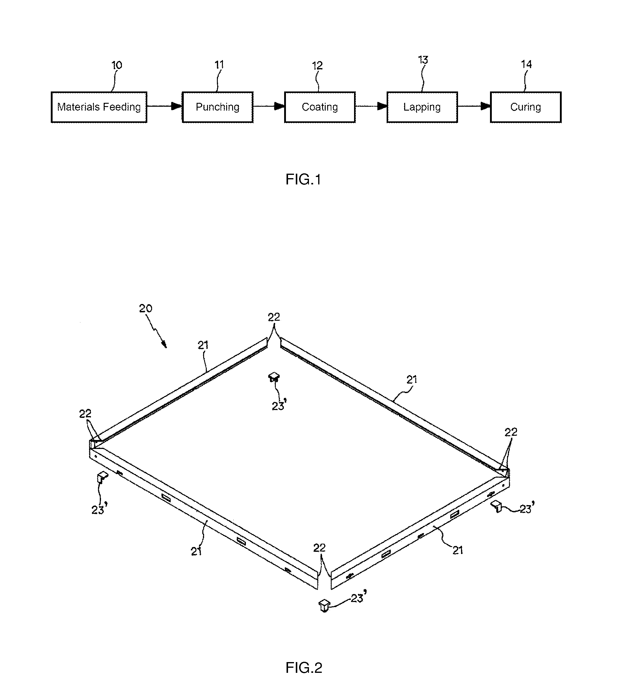
[0030]Referring to FIG. 1, a manufacturing method for a 3C frame includes the following processes: a feeding process 10, a punching process 11, a coating process 12, a lapping process 13, and a curing process 14.

[0031]In the feeding process 10, a material related to a ferrous metal or a non-ferrous metal is fed as the material for formation of a 3C frame; the ferrous metal allows its surface to be plated with zinc, hot-dip galvanized, or other surface treatment; and the non-ferrous metal is related to aluminum alloy or magnesium alloy.

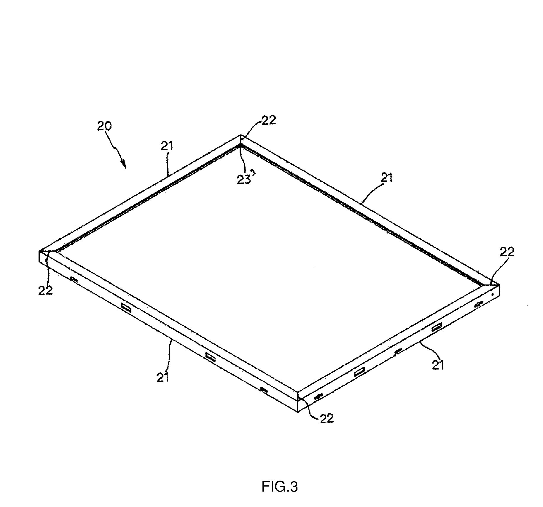
[0032]The punching process 11 is executed in one or multiple of following courses: stamping, forming, and banding; wherein the material fed is punched into a L-shaped side frame 21 or a straight side frame 21; both ends of each side frame 21 are respectively disposed with a lapping portion 22; and it is preferred that a joint 23 is formed at one or a plurality of the lapping portion 22 on the side frame 21; the joint 23 is lapped over the lapping porti...


PUM

PropertyMeasurementUnit
temperatureaaaaaaaaaa
adhesion strengthaaaaaaaaaa
shear strengthaaaaaaaaaa

Abstract

A 3C frame manufacturing method including materials feeding, punching, coating, lapping, and curing processes provides a top quality technical production features of the present invention while avoiding problems of paint peeling or corrosion found with the conventional welding process; and allowing automated production, optimal use of human resources, significantly reduction of manual and labor costs, and shortening of production flow.

Description

BACKGROUND OF THE INVENTION[0001]The present invention is related to a method for manufacturing a frame, and more particularly, to one for manufacturing a 3C frame by gluing a punched frame in conjunction with joints.[0002]Most of conventional 3C frames are usually made of having an entire sheet of material punched into multiple side frames, and those side frames, typically four pieces of side frames, are then welded into a frame using resistance spot welding, laser welding or base welding method. However, the punching and welding processes are found with the following flaws:[0003]1. Extreme waste of material to fail economic benefits since the entire sheet of material is punched while removing or hollowing the central portion.[0004]2. The following disadvantages since the welding job is provided after multiple side frames are punched into shape:[0005]a. The welding job is only made possible for the same type of metal;[0006]b. Surface treatment of the frame can be done after the com...

Claims


Application Information

Patent Timeline
Patent Type & Authority Applications(United States)
IPC IPC(8): B23P17/04
CPCB23P15/00Y10T29/49C09J2400/163C09J5/06
Inventor TSAI, TSUNG-HSUNKEONG, CHI-WAHHUNG, BO-YU
Owner CHENG FWA INDAL
Learn More