
Water heater

a water heater and water tank technology, applied in water heaters, drum steam boilers, lighting and heating apparatus, etc., can solve the problems of high cost, additional parts in the structure, and inefficient transmission of radiation heat to the lower mirror plate, so as to reduce radiation to other parts than the hot water storage chamber, reduce the effect of increasing the combustion air temperature and efficient transmission of hot water

Active Publication Date: 2008-10-30
PALOMA
View PDF11 Cites 5 Cited by
  • Summary
  • Abstract
  • Description
  • Claims
  • Application Information

AI Technical Summary

Benefits of technology

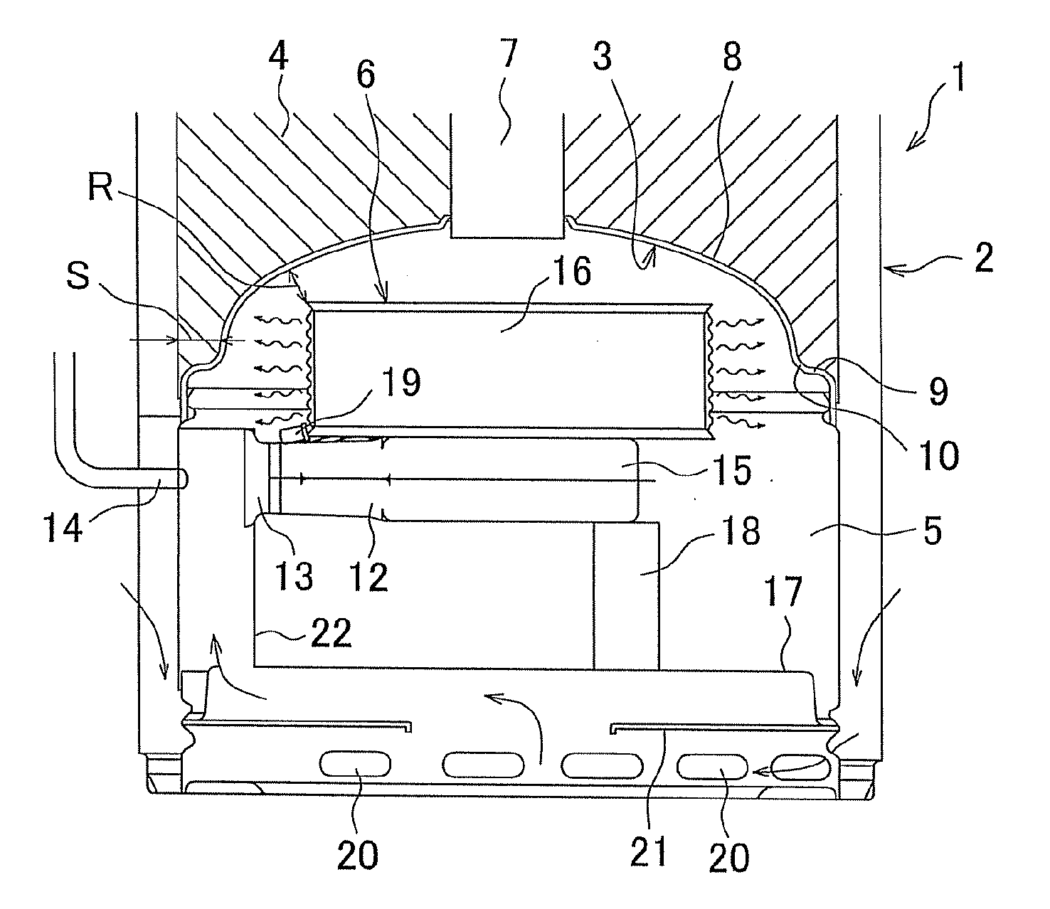
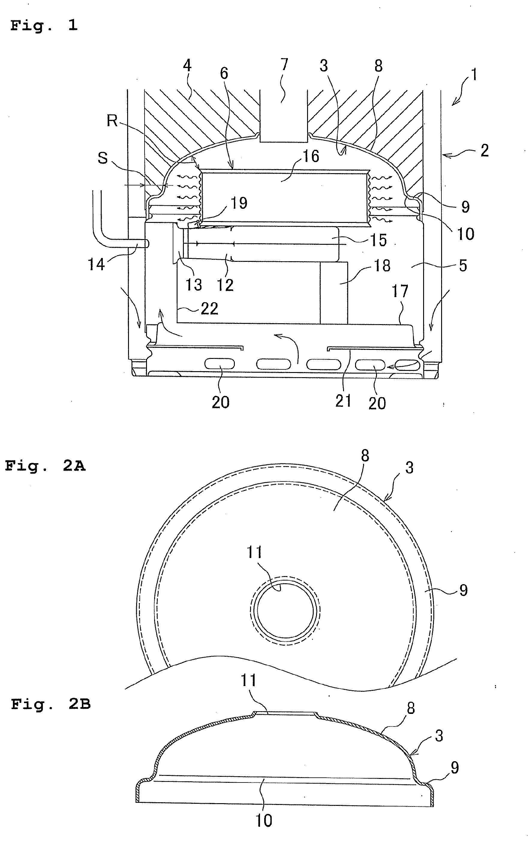
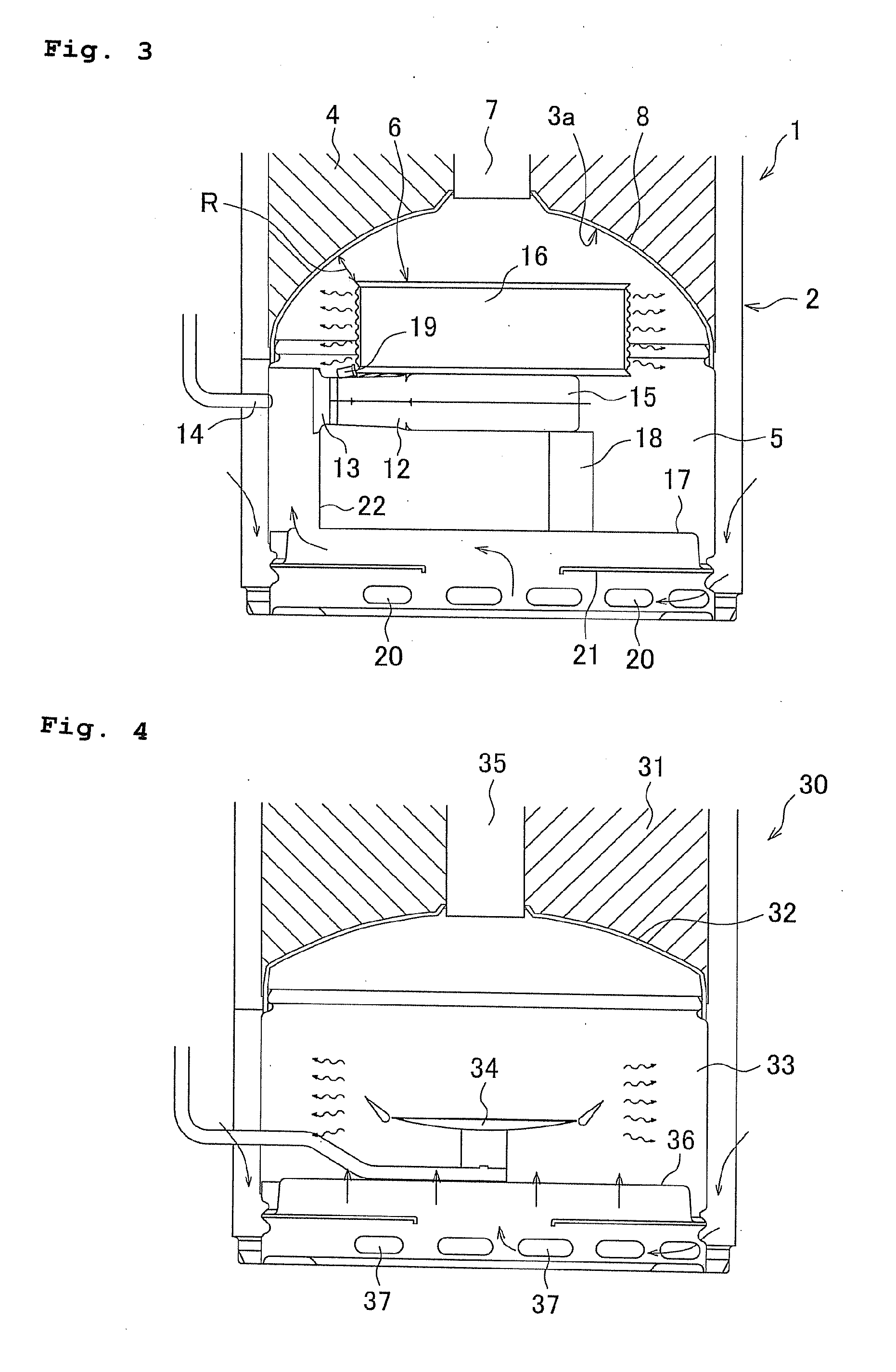
[0005]The conventional burner 34 described in the patent document is a Bunsen burner, and a large combustion space is needed in the combustion chamber 33. Thus, a distance between the burner 34 and the lower mirror plate 32 is long, and radiation heat from the burner 34 is emitted toward an inner surface of the combustion chamber 33 as illustrated with wavy lines. Thus, the radiation heat is not efficiently transmitted to the lower mirror plate 32. When a temperature of combustion air from the air inlet 37 is increased by such radiation heat, a volume of the air is expanded and an amount of primary air to supply to the burner 34 is decreased, which causes the generation of nitrogen oxide. Although an increase of the combustion air temperature can be suppressed by shield of radiation heat with a partition plate or an insulating board, additional parts in the structure causes high cost.
[0006]An object of the present invention is to provide a water heater capable of suppressing an increase of combustion air temperature and suppressing to generate nitrogen oxide with an easy structure.
[0008]A second aspect of the invention, according to the first aspect, is a water heater in which the burner includes a cylindrical burner head as a combustion part and a side surface of the burner head is a combustion surface in order to efficiently transmit radiation heat to hot water in a hot water storage chamber.
[0010]According to the first aspect of the invention, radiation of a burner is efficiently transmitted to hot water in a hot water storage chamber, and radiation to portions other than the hot water storage chamber is decreased. Thus, an increase of the combustion air temperature can be suppressed, and generation of nitrogen oxide is rarely generated. Further, energy loss can be prevented, which improves thermal efficiency. Furthermore, since the height of a burner is only necessary for the water heater, additional parts of the structure such as an insulating board is not necessary, which reduces the cost.
[0011]According to the second aspect of the invention, in addition to the effect of the first aspect, a burner can be arranged closer to an end plate so that a whole periphery of a burner head faces the mirror plate. Thus, radiation heat can be efficiently transmitted to hot water in the hot water storage chamber.
[0012]According to the third aspect of the invention, in addition to the effect of the second aspect, a flowing passage of combustion gas for the burner head between the burner head and the mirror plate is secured to suppress increase of exhaust resistance, and the burner can be arranged at a suitable position.

Problems solved by technology

Thus, the radiation heat is not efficiently transmitted to the lower mirror plate 32.
Although an increase of the combustion air temperature can be suppressed by shield of radiation heat with a partition plate or an insulating board, additional parts in the structure causes high cost.

Method used


Image

  • Water heater
  • Water heater
  • Water heater

Examples


Embodiment Construction

[0017]Embodiments of the present invention will be described below with reference to the drawings.

[0018]FIG. 1 is an explanatory view of a lower portion showing an example of a water heater. A water heater 1 includes a hot water storage chamber 4 and a combustion chamber 5. The hot water storage chamber 4 is provided on an upper side of a cylindrical main body 2 and upper and lower parts of the hot water storage chamber 4 are closed with an upper mirror plate (not illustrated) and a lower mirror plate 3. The combustion chamber 5 has a burner 6 below the hot water storage chamber 4. In addition, the water heater 1 includes a water supply pipe and a hot water supply pipe on an upper side of the hot water storage chamber 4 (both pipes are not illustrated). The water supply pipe is for supplying water into the hot water storage chamber 4, and the hot water supply pipe is for taking hot water out of the hot water storage chamber 4.

[0019]The hot water storage chamber 4 includes an exhaust...


PUM


Abstract

To provide a water heater capable of suppressing an increase of combustion air temperature and suppressing to generate nitrogen oxide with an easy structure. In a water heater, a burner provided in a combustion chamber provided below a hot water storage chamber is an all primary air burner taking in air required for combustion, where the air is mostly primary air. Further, the burner is provided with a supporting plate in the combustion chamber at the height that a part of a burner head is protruded into a space covered by a lower mirror plate.

Description

BACKGROUND OF THE INVENTION[0001]This application claims the entire benefit of Japanese Patent Application Number 2007-119827 filed on Apr. 27, 2007, the entirety of which is incorporated by reference.FIELD OF THE INVENTION[0002]The present invention relates to a water heater, especially a hot water storage type water heater, for heating hot water stored in a hot water storage chamber to a predetermined temperature and keeping the temperature.DESCRIPTION OF THE BACKGROUND ART [0003]As shown in patent document 1, a hot water storage type water heater including a hot water storage chamber on the upper side of a cylindrical main body and a combustion chamber has been known. The hot water storage chamber is formed on an upper side of the cylindrical main body by closing top and bottom thereof with a mirror plate formed with an upward protruded restriction part in the upper and lower directions and has an exhaust passage at a central axis thereof. The combustion chamber with a burner is ...

Claims


Application Information

Patent Timeline
IPC IPC(8): F24H1/24
CPCF24H1/205
Inventor ODA, HIROSHI
Owner PALOMA
Learn More