Solar Collector with Hydrophilic Photocatalytic Coated Protective Pane

a technology of hydrophilic photocatalytic coating and solar collector, which is applied in the direction of solar heat collector safety, solar ray transmission, lighting and heating apparatus, etc., can solve the problems of reducing the efficiency of solar collectors. , to achieve the effect of reducing maintenance costs and improving collection efficiency

Inactive Publication Date: 2008-10-30
JPS INTPROP
View PDF34 Cites 19 Cited by
  • Summary
  • Abstract
  • Description
  • Claims
  • Application Information

AI Technical Summary

Benefits of technology

[0008]It is a feature of the present invention to provide a solar collector with improved collection efficiency in the face of obscuring dust or dirt on the collector's glass cover.
[0009]It is a further feature of the present invention to provide a glass cover for a solar cell array or a solar absorption box with lower maintenance costs.

Problems solved by technology

Because of the protective function of the solar device cover, it will be exposed to contamination which can gradually obstruct the glass covering, resulting in a diminution of the solar energy passing through the cover to the solar device.
To restore the performance of the solar device it is then necessary to periodically clean the glass covers, something that may be cumbersome, time consuming, and costly and potentially unsafe.

Method used


Image

  • Solar Collector with Hydrophilic Photocatalytic Coated Protective Pane
  • Solar Collector with Hydrophilic Photocatalytic Coated Protective Pane

Examples


Embodiment Construction

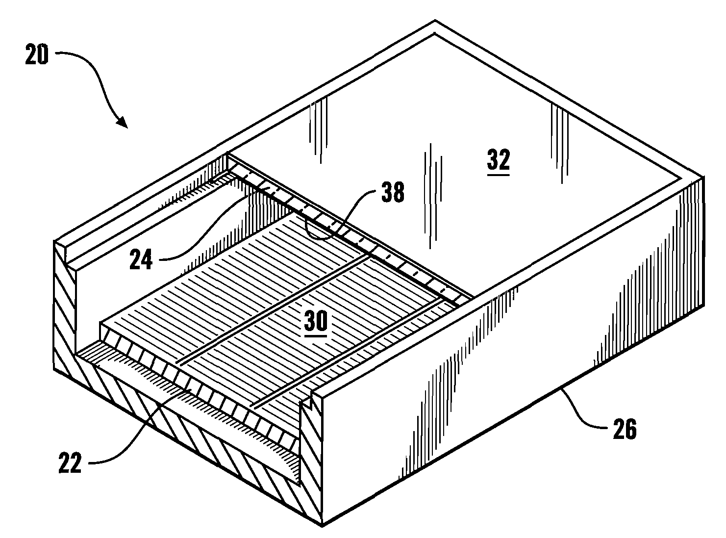
[0013]Referring more particularly to FIGS. 1-2, where like numbers refer to similar parts, a solar cell array module 20 is shown in FIG. 1. The solar cell array module 20 comprises a plurality of solar cells 22 positioned beneath a glass pane 24. The glass pane 24 together with an enclosure or box 26 protects the solar cells 22 from the environment. The glass pane 24 prevents rain, moisture and possibly corrosive elements from contacting the solar cells 22 which may corrode or short out in the presence of moisture. However to function, that is to generate power from the sun's rays, the glass pane is necessary in order to allow the sun's rays to reach the photoelectric surface 30 of the solar cells. The cost of solar cells, while continuing to decline, is still substantial. Therefore, to minimize the total cost and the number of solar cells needed it is important to maximize the amount of sunlight reaching the photoelectric surface 30 of the solar cells 22.

[0014]Although the module 2...


PUM

PropertyMeasurementUnit
contact angleaaaaaaaaaa
thicknessaaaaaaaaaa
water droplet contact angleaaaaaaaaaa

Abstract

A solar collector which is illuminated by the sun through a glass panel wherein the glass panel is constructed of glass without low-e coatings with a first surface coating of a magnetron sputtered vapor deposition coating consisting primarily of titanium dioxide. The titanium dioxide achieves a hydrophilic photocatalytic surface to produce a solar collector which is self-cleaning for increased solar energy transmittance with less cleaning cost.

Description

CROSS REFERENCES TO RELATED APPLICATIONS[0001]Not applicable.STATEMENT AS TO RIGHTS TO INVENTIONS MADE UNDER FEDERALLY SPONSORED RESEARCH AND DEVELOPMENT[0002]Not applicable.BACKGROUND OF THE INVENTION[0003]The present invention relates to solar energy devices in general, and more particularly to the protective glass coverings of such devices through which solar radiation enters.[0004]Solar radiation striking the earth's surface can be utilized in various fashions to provide for heating and electrical needs. Solar thermal collectors expose a working fluid to solar radiation, and then transport that liquid for use either directly or for heating some other fluid in a heat exchanger. Solar photovoltaic cells convert the solar radiation to electricity which is then either immediately used, stored in some fashion, or returned to the power grid. For purposes of this application, “solar collectors” encompasses both solar thermal collectors and solar photovoltaic cells. Typically solar coll...

Claims


Application Information

Patent Timeline
Patent Type & Authority Applications(United States)
IPC IPC(8): F24J2/50
CPCC03C17/2456C03C2217/212C03C2217/71C03C2217/75C03C2218/156F24J2/461F24J2/505Y02E10/40F24S80/52F24S40/20
Inventor BERANEK, GERALD D.
Owner JPS INTPROP
Why Eureka
Try Eureka