Concrete Sideform System

a sideform system and concrete technology, applied in the direction of moulds, mould fastening means, shaping building parts, etc., can solve the problems of inability to produce crisp sharp edges, bulky extrusion, and general bulkiness, and achieve simple, easy and cost-effective changes, and improve surface finish.

Active Publication Date: 2008-10-30
SRB CONSTR TECH
View PDF27 Cites 8 Cited by
  • Summary
  • Abstract
  • Description
  • Claims
  • Application Information

AI Technical Summary

Benefits of technology

[0017]The inserts may be formed to impart any desired shape to the edge of the concrete panel. The inserts may extend to cover part or all of the first face of the frame. The inserts may also add height to the wall. Alternatively, extension pieces may be used to add height to the wall by fitting to the frame formations and themselves having formations to releasably receive an insert. In this way the invention may enjoy the ability to simply, easily and cost effectively change the thickness of the concrete panel being cast without having to replace the sideform.
[0018]An extension along the rear of the capping inserts may be used to protect the securing formations from concrete spillage.
[0019]A formation, such as a notch or step may be provided in the upper surface of the capping inserts directly above the first face, to assist in setting out the sideforms correctly on the casting bed.
[0020]An upper edge may be provided along the top of the capping inserts to assist in forming a clean top edge to the poured concrete.
[0021]A slurry catching channel may be incorporated into the capping inserts to catch concrete spillage and slurry resultant from pouring, levelling (screeding) and finishing the concrete panel. The channel may also help stop excess concrete from spilling onto the casting bed and wall fixing mechanisms.
[0022]A scrapping edge may also be incorporated into the capping inserts. This edge assists in removing excess concrete from the concrete screed trowel that is used to level the concrete, both as it moves across the sideform from the concrete surface, and once again as the trowel travels across the sideforms back onto the concrete surface. This is important in that it reduces the problem of excess concrete being left on the concrete surface. It also keeps the screed trowel a lot cleaner thus allowing for a much better surface finish eliminating drag marls left by excess concrete on the screed.

Problems solved by technology

Due to space constraints, site casting frequently involves pouring several panels one on top of another.
It is virtually impossible to produce a crisp sharp edge on cast concrete, since concrete is made up of granular particles and the sharpness of the corner is governed by the size of the particles.
A sharp edge would also highlight formwork that is not perfectly straight and true, and also such an edge would chip very easily.
Folded steel plate sideforms are generally used for precasting, but not for tilt-up as they are too heavy.
Some of these have different angles of splay, but they are generally bulky and expensive to extrude.
This is wasteful, slow, extremely labour intensive and does not produce a nice accurate finish.
The bolting is time consuming and the resulting structure is very heavy and difficult to manoeuvre.
This technique is prone to problems when excess concrete falls into the channels and sets there.
No casting bed or surface is perfectly true and flat, whether it is made from steel, concrete or any other material.
Gaps between the bed and the sideforms result in bleeding of water and fine particles.
The result is weak and crumbly patches in the panel that have to be repaired.
Although this is effective in sealing leaks, it gives rise to substantial costs in time and labour to scrape and grind the cured silicone residue from the casting beds and sideforms before they can be used again.
It also causes wear and tear and damage to both surfaces.
When a hand or power trowel is then used to finish off the concrete surface these implements do not cut the concrete surface and tend to ride the areas where the concrete residue has been deposited, which results in these areas being slightly elevated.
There is also the cost in time, labour and productivity in cleaning the excess concrete spillage from the casting bed.

Method used


Image

  • Concrete Sideform System
  • Concrete Sideform System
  • Concrete Sideform System

Examples


Embodiment Construction

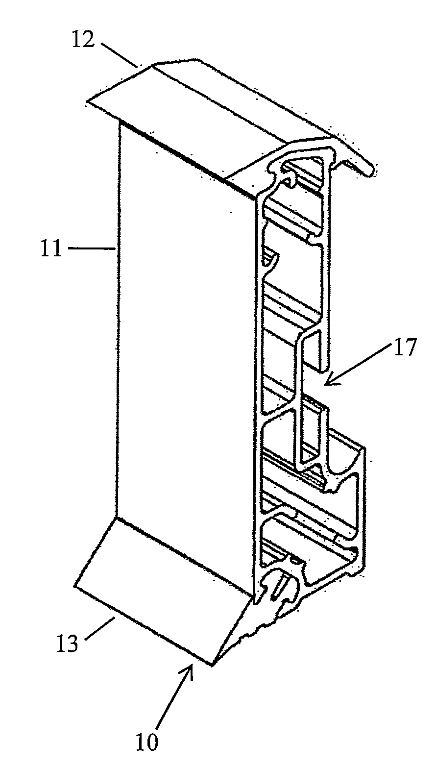
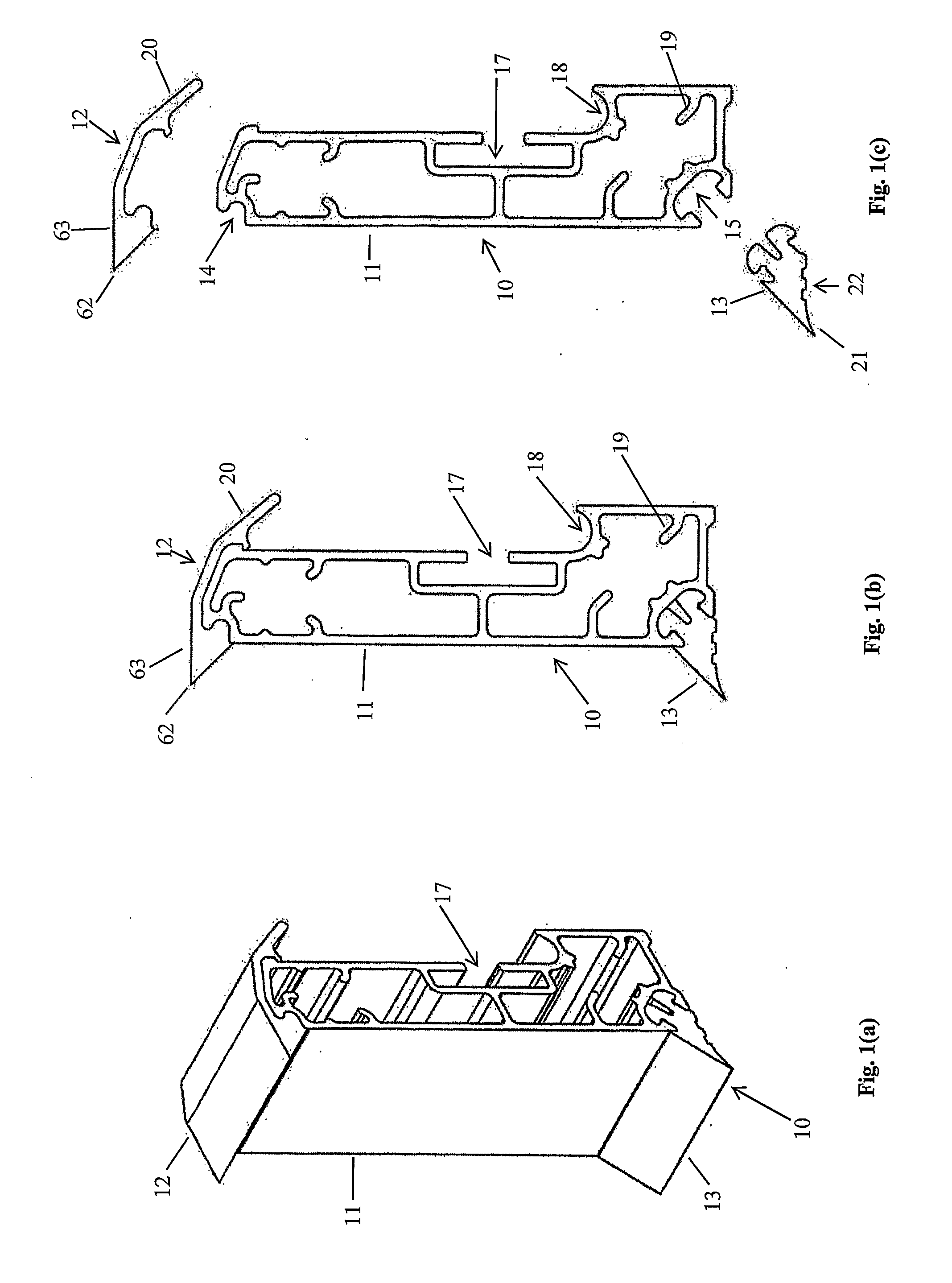
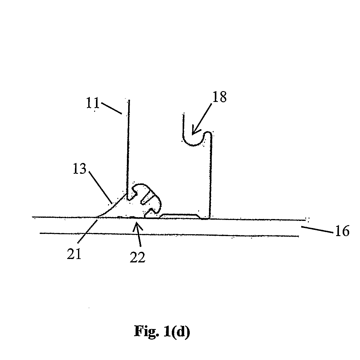
[0047]Referring first to FIG. 1, sideform 10 is a mono-sided composite sideform for factory casting; it cannot be used upside down. The sideform is comprised of an extruded aluminum (or plastics) frame 11, a capping insert 12 made from extruded from alloy or polymer, and a base edge insert 13 made from plastics or rubber. Formations 14 and 15 in the top and bottom of frame 11 cooperate with formations on the inserts 12 and 13 to releasably connect them together. When the inserts are attached to the frame they create a shaped edge to the poured concrete panel; the edge has a vertical section where it meets the frame and corners chamfered at 45° along its upper and lower edges.

[0048]A ‘T’-shaped slot 17 in the back of the sideform is provided for securing it to the bed. This formations allow a bolt or uni-bolt to be inserted, or alternatively a plate with threaded lugs. The sideform is then secured to a factory casting bed using magnets, or to a panel cast underneath with steel angles...


PUM

PropertyMeasurementUnit
thicknessesaaaaaaaaaa

Abstract

This invention concerns a concrete side form system suitable for factory casting or site casting concrete. The side form (10) comprises a substantially rigid longitudinally extending wall. The wall has a first face to define the edge profile of a concrete panel poured onto a casting bed (16) bounded by the wall and a second face opposite the first face having formation to enable the wall to be secured to the casting bed. The wall comprises a longitudinally extending frame having formation along at least one of its edges to removably receive a removable longitudinal insert (13) to provide a shape along an edge of the concrete panel. The removable inserts (12, 13) provide the system with the ability to simply, easily and cost effectively change the edge profile of concrete poured against the side form. Architects can use the invention to specify standard or non standard edge profiles and achieve a much more diverse range of aesthetic finishes to the concrete edges without the cost being prohibitive.

Description

TECHNICAL FIELD[0001]This invention concerns a concrete sideform system. The system is suitable for factory casting (‘precasting’) or site casting (‘tilt-up’) concrete.BACKGROUND ART[0002]Factory casting, or precasting, of concrete panels usually takes place on a large steel platform (casting bed) in a precast yard. The sizes and shapes of the panels are determined by sideforms that are arranged on the platform, and concrete is poured into the space defined by the sideforms. When the concrete is dry the panels are transported for installation.[0003]Alternatively, concrete panels may be poured on-site, or tilt-up. In this case the panels are cast either on concrete slabs or on transportable steel beds. Again sideforms are used to define the size and shape. The panels are subsequently lifted into position using a crane. Due to space constraints, site casting frequently involves pouring several panels one on top of another. After the lowermost panel is dry it is coated with a release a...

Claims


Application Information

Patent Timeline
Patent Type & Authority Applications(United States)
IPC IPC(8): E04G9/10E04G9/05E04G11/06E04G9/06B28B7/00B28B7/02E04G11/08E04G13/00E04G15/02
CPCB28B7/0011B28B7/0014B28B7/0085B28B7/02E04G13/00E04G9/08B28B7/06E04G9/06E04G9/05B28B7/348E04G15/02E04G17/004
Inventor SLADOJEVIC, ROBERTGIROTTO, STEVENDELEON, CRAIG
Owner SRB CONSTR TECH
Why Eureka
Try Eureka