

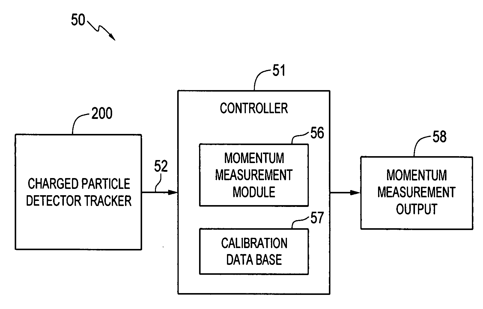
Measuring momentum for charged particle tomography
a technology of momentum measurement and charged particle, which is applied in the direction of material analysis, heat measurement, instruments, etc., can solve the problem of not being able to shield the material thickness practicably, and achieve the effect of reducing nois
- Summary
- Abstract
- Description
- Claims
- Application Information
AI Technical Summary
Benefits of technology
Problems solved by technology
Method used
Image

Examples
Embodiment Construction
[0038]The particular values and configurations discussed in these non-limiting examples can be varied and are cited merely to illustrate at least one embodiment of the present invention and are not intended to limit the scope of the invention.
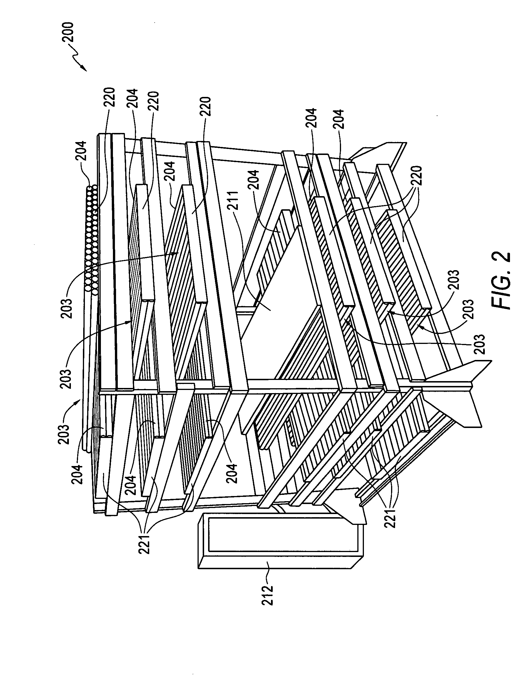
[0039]Technical features described in this application can be used to construct various particle detection systems. For example, a particle detection system for detecting muons as the charged particles can include an object holding area for placing an object to be inspected, a first set of position sensitive muon detectors located on a first side of the object holding area to measure positions and angles of incident muons towards the object holding area, a second set of position sensitive muon detectors located on a second side of the object holding area opposite to the first side to measure positions and angles of outgoing muons exiting the object holding area, and a signal processing unit, which may include, e.g., a microprocessor, to receive...
PUM
 Abstract
Description
Claims
Application Information