Power Tool

a technology of power tools and power supplies, applied in the field of power tools, can solve the problems of reducing efficiency or malfunction, large heat generation of inverter circuit boards (motor-driving circuit boards), and large output transistors of brushless motors

Active Publication Date: 2008-10-30
HITACHI KOKI CO LTD
View PDF11 Cites 89 Cited by
  • Summary
  • Abstract
  • Description
  • Claims
  • Application Information

AI Technical Summary

Benefits of technology

[0009]This and other object of the present invention will be attained by a power tool including a housing, a brushless motor, and a cover member. The housing has an air intake hole and an air exhaust hole formed therein, the housing having an inner surface. The brushless motor has an outer surface disposed in the housing, a first endface near the air intake hole, and a second endface near the air exhaust hole. The cover member covers at least one of the first endface and the second endface for preventing dust from entering the brushless motor. The inner surface of the housing and outer surface of the brushless motor define a circulation path providing communication between the air intake hole and the air exhaust hole.

Problems solved by technology

However, the relatively large power loss that occurs when the brushless motor is driven produces heat that can affect the motor operations, leading to a reduction in efficiency or malfunctions.
In fact, loss in a stator unit is a primary source of heat generation and comprises copper loss occurring when an electric current flows through the stator coil, and iron loss occurring in the stator core material due to changes in magnetic flux density.
Further, output transistors in the brushless motor constituting switch elements for an inverter circuit board (motor-driving circuit board) generates a large amount of heat when supplying a large current drive signal to the stator coil.
However, while the above mechanisms are capable of cooling the stator and inverter circuit board of a brushless motor by introducing external air, circulating external air through the stator invites dust particulate in the air to accumulate on the rotor and stator.

Method used


Image

  • Power Tool
  • Power Tool
  • Power Tool

Examples


Embodiment Construction

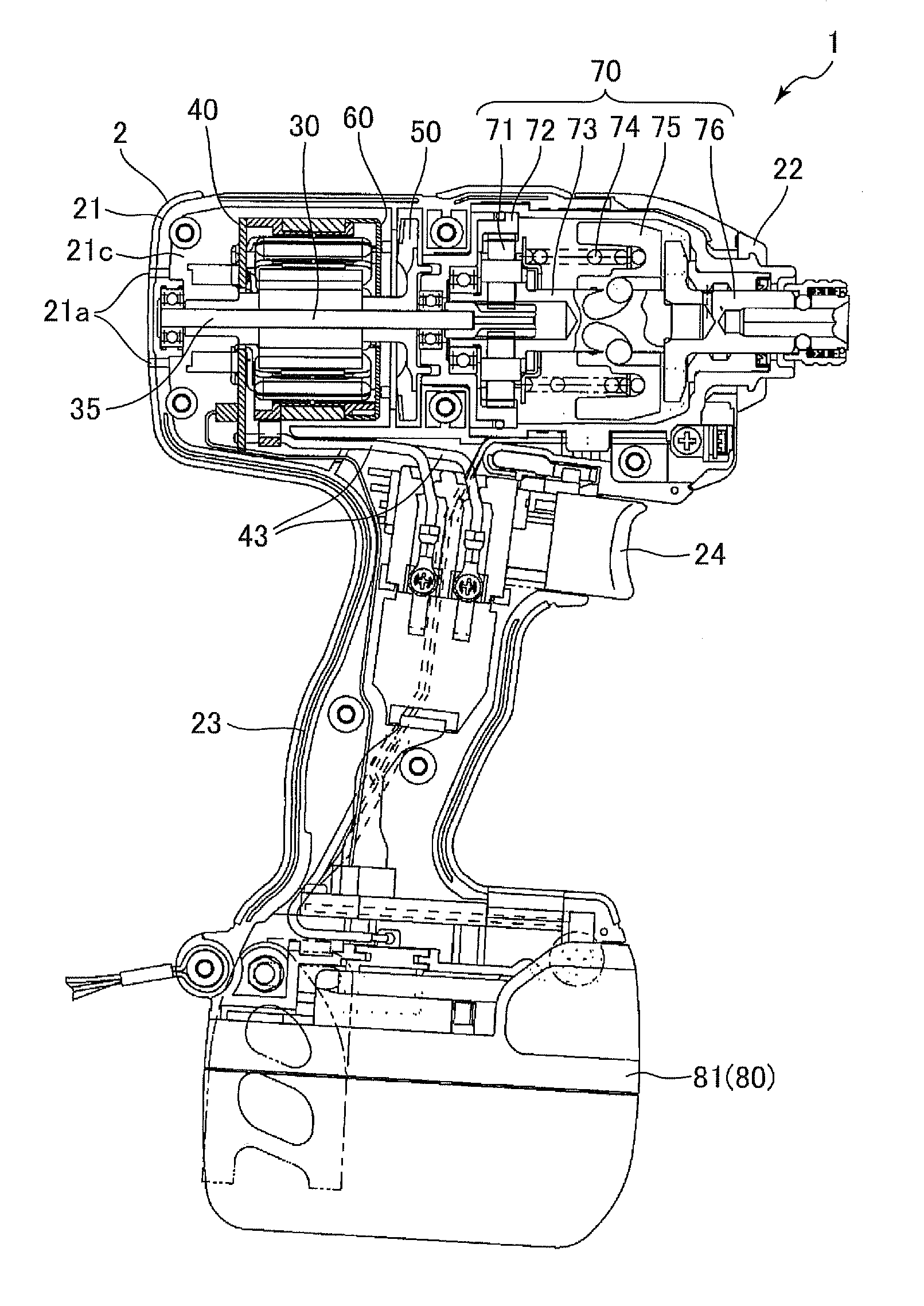
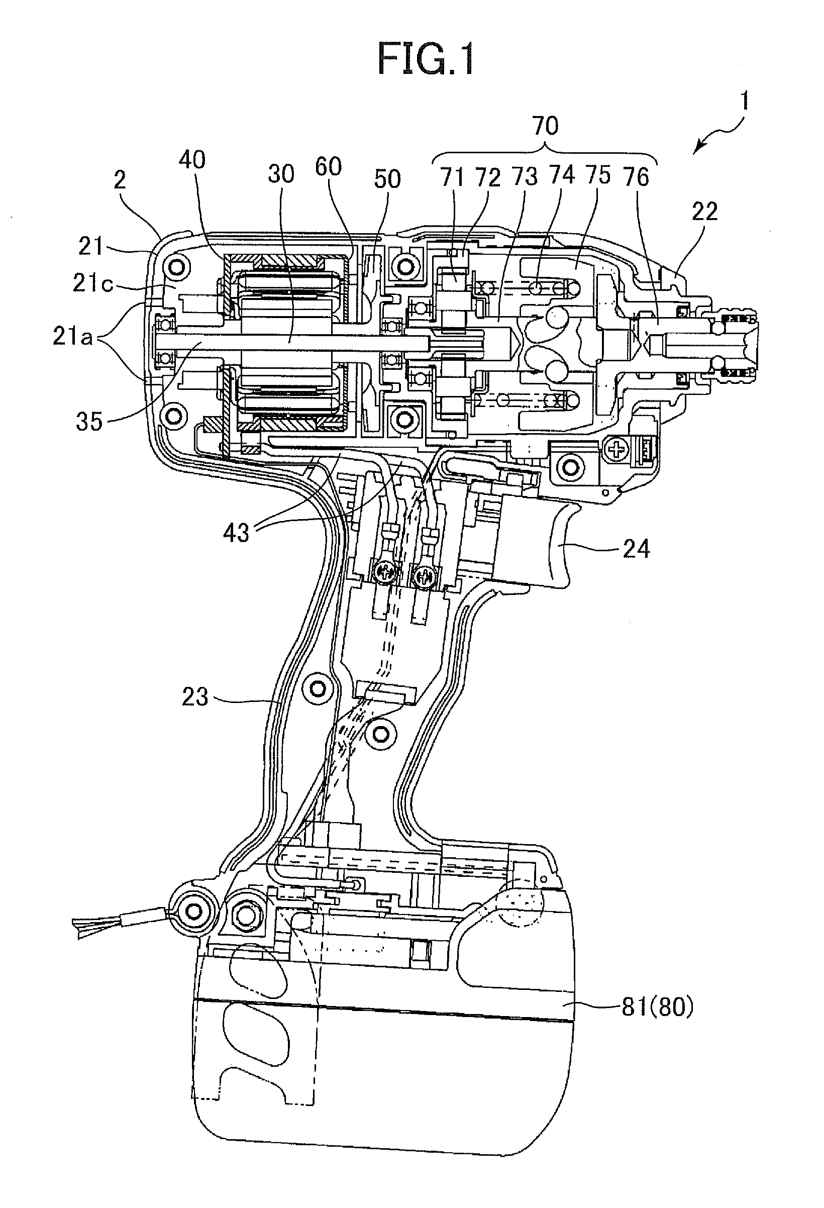
[0031]A power tool according to an embodiment of the present invention will be described while referring to FIGS. 1 through 11. FIG. 1 shows an impact driver 1 serving as the power tool of the embodiment. First, the overall structure of the impact driver 1 will be described with reference to FIG. 1.

[0032]The impact driver 1 has a housing 2 constituting the outer shell thereof. The housing 2 is configured of a motor housing 21, a power transmission housing 22 formed continuously with the motor housing 21, and a handle housing 23 extending downward from the motor housing 21 and the power transmission housing 22.

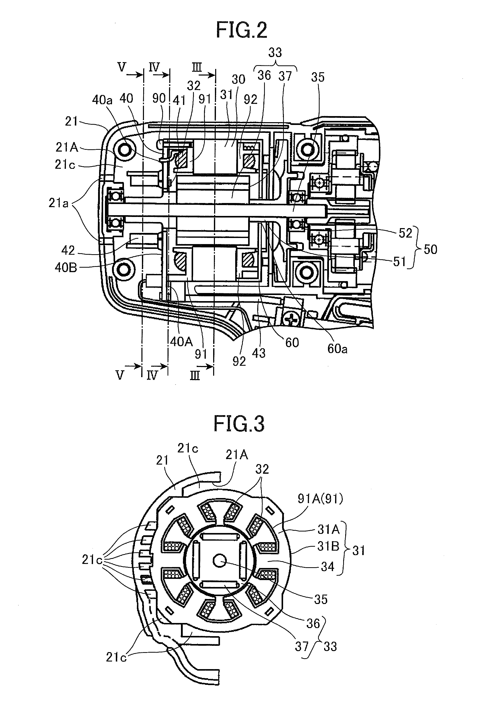
[0033]The motor housing 21 has a cylindrical shape and accommodates a brushless motor 30 serving as a drive source, a circuit board 40 for controlling the brushless motor 30, a fan 50, and a cover 60 for preventing dust from entering the brushless motor 30. Air intake holes 21a are formed in the rear of the motor housing 21 for introducing external air into the housing 2, and e...


PUM


Abstract

A power tool includes a housing, a brushless motor, and a cover member. The housing has an air intake hole and an air exhaust hole formed therein, the housing having an inner surface. The brushless motor has an outer surface disposed in the housing, a first endface near the air intake hole, and a second endface near the air exhaust hole. The cover member covers at least one of the first endface and the second endface for preventing dust from entering the brushless motor. The inner surface of the housing and outer surface of the brushless motor define a circulation path providing communication between the air intake hole and the air exhaust hole.

Description

CROSS REFERENCE TO RELATED APPLICATION[0001]This application claims priority from Japanese Patent Application No. 2007-118834 filed Apr. 27, 2007, Japanese Patent Application No. 2007-140239 filed May 28, 2007, and Japanese Patent Application No. 2007-143164 filed May 30, 2007. The entire content of each of these priority applications is incorporated herein by reference.BACKGROUND OF THE INVENTION[0002]1. Field of the Invention[0003]The present invention relates to a power tool employing a brushless motor.[0004]2. Description of the Related Art[0005]Brushless motors have commonly been employed in power tools to achieve a more compact design because brushless motors do not require an electrical connection using a brush and commutator for a rotor mounted on a rotational shaft. However, the relatively large power loss that occurs when the brushless motor is driven produces heat that can affect the motor operations, leading to a reduction in efficiency or malfunctions. In fact, loss in ...

Claims


Application Information

Patent Timeline
Patent Type & Authority Applications(United States)
IPC IPC(8): H02K7/14
CPCH02K5/20H02K7/145H02K9/06H02K2211/03B25F5/02H02K5/207
Inventor YOSHIDA, KENICHIROUOOMORI, KATSUHIROKOMURO, YOSHIHIROIWATA, KAZUTAKA
Owner HITACHI KOKI CO LTD
Why Eureka
Try Eureka