Polymer Light-Emitting Diode

a light-emitting diode and polymer technology, applied in the direction of discharge tube/lamp details, luminescent screen of discharge tube, thermoelectric device, etc., can solve the problems of difficult to match with the work function of anode and/or cathode, and achieve low sensitivity to high temperature, long expected life, and quick response

Inactive Publication Date: 2008-10-30
KONINKLIJKE PHILIPS ELECTRONICS NV
View PDF2 Cites 10 Cited by
  • Summary
  • Abstract
  • Description
  • Claims
  • Application Information

AI Technical Summary

Benefits of technology

[0005]An object of the present invention is to provide a light-emitting diode having a quick response without the manufacturing costs and the large temperature sensitivity associated with the prior art LECs having “frozen” ion gradients.

Problems solved by technology

Such polymers may have a large band gap, which makes it difficult to match with the work function of the anode and / or the cathode.

Method used


Image

  • Polymer Light-Emitting Diode
  • Polymer Light-Emitting Diode
  • Polymer Light-Emitting Diode

Examples


Embodiment Construction

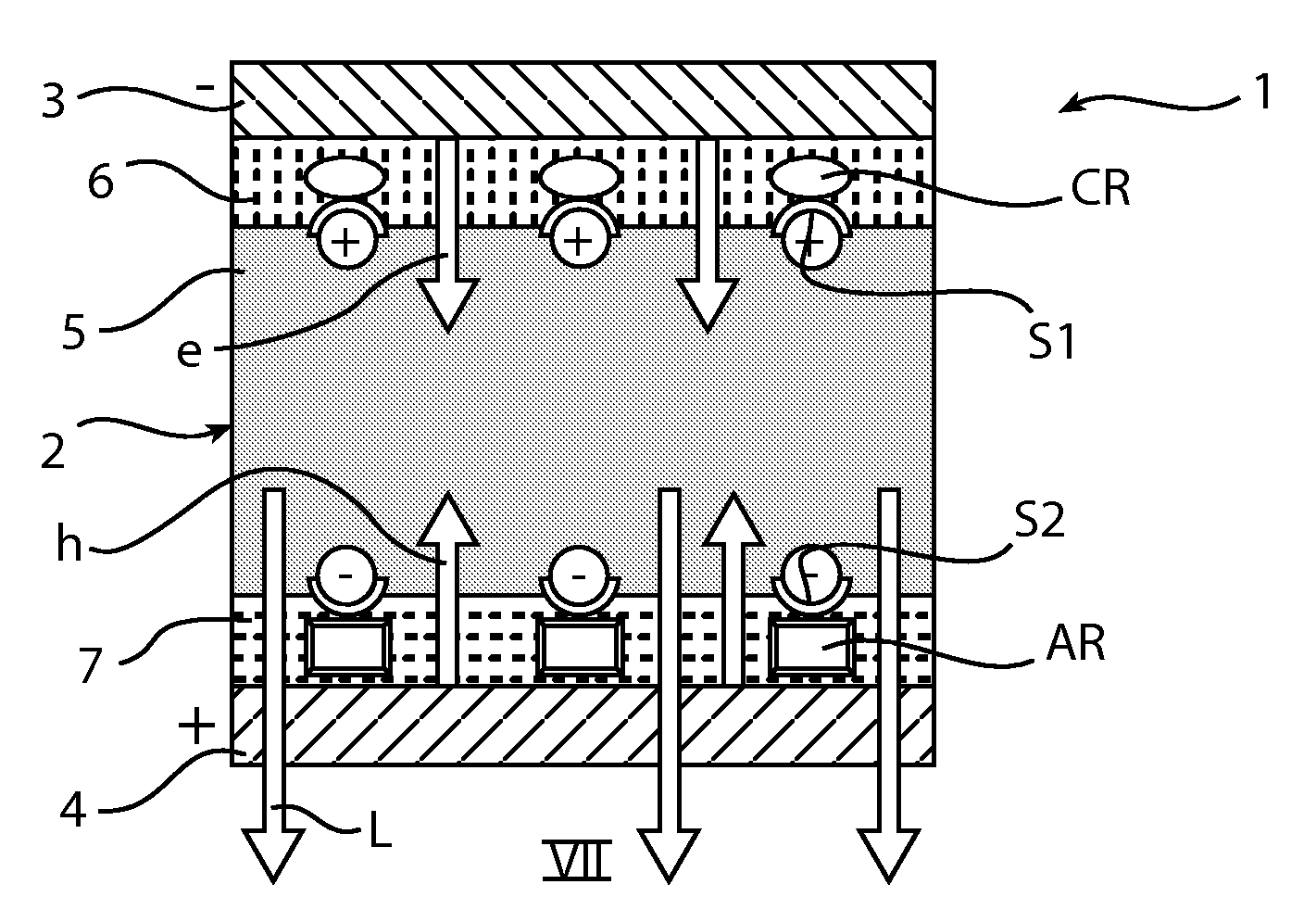
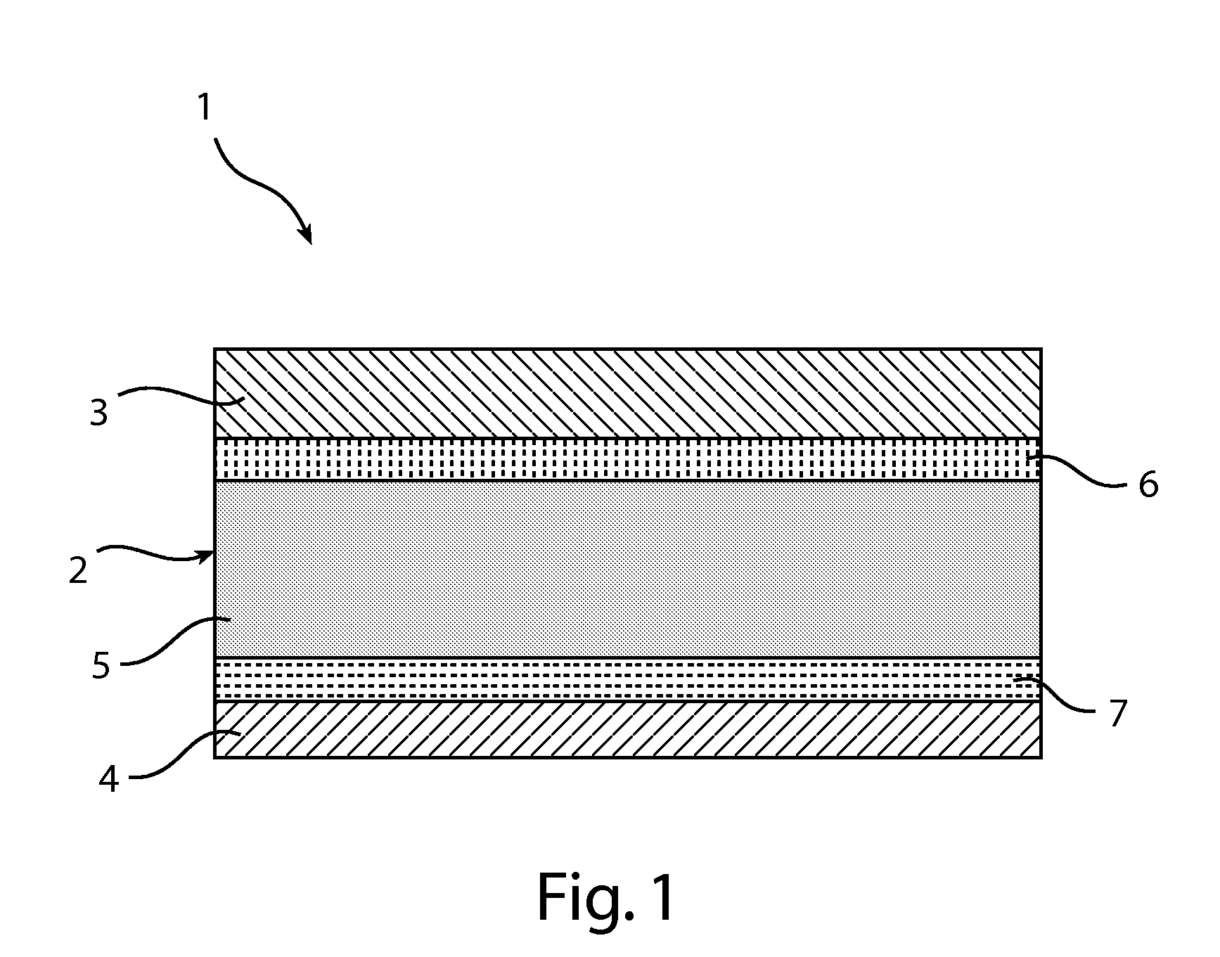
[0037]FIG. 1 shows a light-emitting diode 1 according to the invention. The diode 1 has a laminate structure 2 and comprises a first electrode 3, a second electrode 4 and, positioned between the first electrode 3 and the second electrode 4, a light-emitting layer 5. The diode 1 is provided on a substrate (not shown in FIG. 1), which provides the diode 1 with mechanical support and includes the connections for the electrodes 3, 4.

[0038]The first electrode 3 works as a cathode when the diode 1 is subjected to an electrical field in forward bias. The first electrode 3 is made from a high work function material, for example gold, silver, aluminium or indium tin oxide (ITO). Examples of other alternative electrode materials could be found in, for example, the U.S. Pat. No. 5,682,043 granted to Pei et al. describing light-emitting electrochemical cells in general.

[0039]The second electrode 4 works as an anode when the diode 1 is subjected to an electrical field in forward bias. The second...


PUM


Abstract

A light-emitting diode (1) has a first electrode (3), a second electrode (4), a light-emitting layer (5) which comprises a matrix, and ions. A layer (6) of a cation receptor (CR) is positioned adjacent to the first electrode (3), has captured cations, and has generated immobilized cations (+). A layer (7) of an anion receptor (AR) is positioned adjacent to the second electrode (4), has captured anions, and has generated immobilized anions (−). The ion gradients provide for quick response in emission of light (L) when the diode (1) is exposed to a forward bias. A diode (1) is manufactured by first forming a laminate (2) of the above structure. The laminate (2) is exposed to a forward bias to make the ions become immobilized at respective sites (S1, S2) of the respective receptors (CR, AR).

Description

FIELD OF THE INVENTION[0001]The present invention relates to a light-emitting diode comprising a first electrode, a second electrode and a light-emitting layer being positioned between the two electrodes and comprising a matrix.[0002]The present invention also relates to a method of forming a light-emitting diode having a first electrode, a second electrode and a light-emitting layer being positioned between the two electrodes and comprising a matrix.BACKGROUND OF THE INVENTION[0003]Polymer light emitting electrochemical cells (LEC), which are useful in, among other applications, organic electro-luminescent flat displays and large area light sources, have the function of providing light emission upon an applied voltage without the need for a sensitive low work function metal cathode, which is needed in normal polymer light emitting diodes (PLED). In an LEC a solid electrolyte provides, upon the application of a voltage, the ion gradients needed for the injection of electrons from th...

Claims


Application Information

Patent Timeline
Patent Type & Authority Applications(United States)
IPC IPC(8): H01J1/62H01L35/24H01L33/26H01L33/00
CPCH01L51/5032H10K50/135H05B33/18H05B33/10H05B33/14
Inventor MEIJER, EDUARD JOHANNESMEULENKAMP, ERIC ALEXANDERKURT, RALPHKLINK, STEVE
Owner KONINKLIJKE PHILIPS ELECTRONICS NV
Why Eureka
Try Eureka