Voltage level shifter and buffer using same

buffer technology, applied in the direction of multiple-port active network, electric pulse generator, automatic control, etc., can solve the problems of limiting the frequency range for which a voltage level shifter is useful, and often losing efficiency to direct current (dc) power consumption

Active Publication Date: 2008-10-30
MOSAID TECH
View PDF57 Cites 23 Cited by
  • Summary
  • Abstract
  • Description
  • Claims
  • Application Information

AI Technical Summary

Benefits of technology

[0003]An impact of a voltage level shifter with an input transistor pair, a cross-coupled load chain transistor pair and a pair of current sources is that power consumption may be reduced through the use of the cross-coupled load chain transistor pair to minimize the DC current component present in known voltage level shifters. In specific embodiments, feedback elements may be used to minimize delays in signal transitions.

Problems solved by technology

It is challenging to provide a voltage level shifter allowing for an efficient transition from, for instance, a core power supply voltage of a chip to an output buffer of the chip.
Efficiency is often lost to direct current (DC) power consumption.
Additionally, delays in signal transition from low to high or high to low can limit the frequency range for which a voltage level shifter is useful.

Method used


Image

  • Voltage level shifter and buffer using same
  • Voltage level shifter and buffer using same
  • Voltage level shifter and buffer using same

Examples


Embodiment Construction

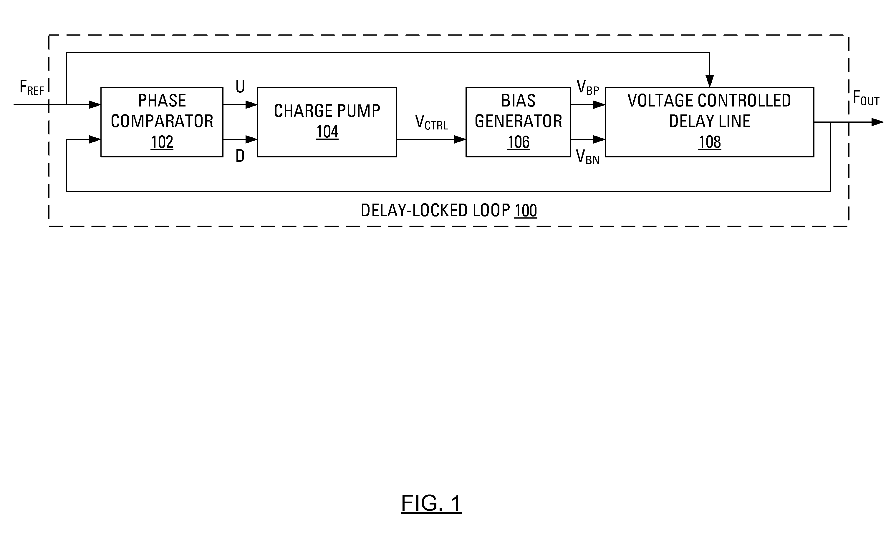
[0021]FIG. 1 presents a schematic illustration of a typical delay-locked loop (DLL) 100 as presented in John G. Maneatis, “Low-Jitter Process-Independent DLL and PLL Based on Self-Biased Technique”, IEEE JSSC VOL. 31, No 11, November 1996, pp. 1723-1732 (hereinafter “Maneatis”). Maneatis indicates that a self-biased DLL is constructed by taking advantage of the control relationship offered by a typical DLL. The typical DLL 100 includes a phase comparator 102, a charge pump 104, a loop filter, a bias generator 106 and voltage controlled delay line (VCDL) 108. The negative feedback in the loop adjusts the delay through the VCDL 108 by integrating the phase error that results between a periodic reference input, FREF, and output, FOUT, from the VCDL 108. Once in lock, the VCDL 108 will delay the reference input, FREF, by a fixed amount to form the VCDL output such that there is no detected phase error between FREF and FOUT.

[0022]In operation, the phase comparator 102 receives the AC ref...


PUM


Abstract

A voltage level shifter with an input transistor pair, a cross-coupled load chain transistor pair and a pair of current sources, effects reduced power consumption through the use of the cross-coupled load chain transistor pair to minimize the DC current component present in known voltage level shifters. In specific embodiments, feedback elements may be used to minimize delays in signal transitions. A reference voltage that corresponds to a current capability of the input transistor pair may be used to regulate the current sources in the load chain. Changes in a swing of the input signal voltage received by the input transistor pair may be reflected in corresponding changes to the reference voltage. The voltage level shifter may be of particular use in a buffer.

Description

BACKGROUND OF THE INVENTION[0001]When multiple circuits are used together, it is often the case that the voltage level for a logical “high” varies from circuit to circuit. For example, the value of a parameter called Vdd may be representative of a core supply voltage for an Application Specific Integrated Circuit (ASIC) chip. Additionally, the value of a parameter called supply voltage Vddq may be representative of a supply voltage for input / output buffers. Furthermore, the value of a parameter called VDDQ may be representative of a supply voltage to output buffers of a chip.[0002]It is challenging to provide a voltage level shifter allowing for an efficient transition from, for instance, a core power supply voltage of a chip to an output buffer of the chip. Efficiency is often lost to direct current (DC) power consumption. Additionally, delays in signal transition from low to high or high to low can limit the frequency range for which a voltage level shifter is useful.SUMMARY[0003]...

Claims


Application Information

Patent Timeline
Patent Type & Authority Applications(United States)
IPC IPC(8): H03L5/00
CPCH03L7/0812H03K3/35613H03L7/0816H02M3/155H03H11/02H03K19/0185
Inventor VLASENKO, PETER A.
Owner MOSAID TECH
Why Eureka
Try Eureka