Backlight module

a backlight module and backlight technology, applied in lighting and heating apparatus, lighting device details, instruments, etc., can solve the problems of reducing the display quality of the lcd, affecting the light path, so as to improve the light efficiency of the light guide plate assembly, and increase the air volume

Inactive Publication Date: 2008-10-30
BEIJING BOE OPTOELECTRONCIS TECH CO LTD
View PDF3 Cites 16 Cited by
  • Summary
  • Abstract
  • Description
  • Claims
  • Application Information

AI Technical Summary

Benefits of technology

[0011]Since the light diffusing particles in the upper light guide plate can change the direction of the incident light, the light incident into the upper light guide plate can be emitted directly from the upper surface of the light guide plate assembly. The lower surface of the lower light guide plate can also change the direction of the light incident into the lower light guide plate by the concave or convex microstructures such that the light incident into the lower light guide plate can be either directed upward to enter the upper light guide plate or reflected onto the underlying reflection film. Most of the light reflected onto the reflection film can be in turn reflected by the reflection film and transmitted through the upper light guide plate, and then emitted from the upper surface of the light guiding plate assembly. As such, the light efficiency of the light guide plate assembly is greatly improved.
[0012]Since the light incident surface of the light guide plate assembly is formed as a bended or curved surface compared with the plane surface in the conventional light guide plate, the light incident direction entering the light guide plate assembly is changed so as to improve the light efficiency of the light guide plate assembly. Furthermore, the space containing the light source is increased accordingly to provide more air volume for better heat dissipation of the backlight module. Therefore, the warping of the light guide plate as well as warping of the optical films is significantly reduced.
[0013]In addition, a prism film can be omitted for a backlight module with the light guide plate according to the present embodiment due to the high light efficiency of the light guide plate assembly, thus reducing or even eliminating the defects associated the prism film, such as a poor display quality due to a defective backlight module due to scratching or white dot, etc.

Problems solved by technology

The brightness of the backlight module is typically enhanced by the prism film; however, the prism film is expensive and also suffers from inevitable defects during its operation.
For example, the prism film tends to warp when heated, and the prisms thereon tend to be scratched, which gives rise to white dots on the display screen and thus lowers the display quality of the LCD.
Furthermore, energy loss approaches 30% in the light path from entering the light guide plate to exiting the light guide plate.
But such type of the light guide plate is expensive since it is made by the injection molding process, therefore the application thereof is limited.

Method used


Image

  • Backlight module
  • Backlight module

Examples


first embodiment

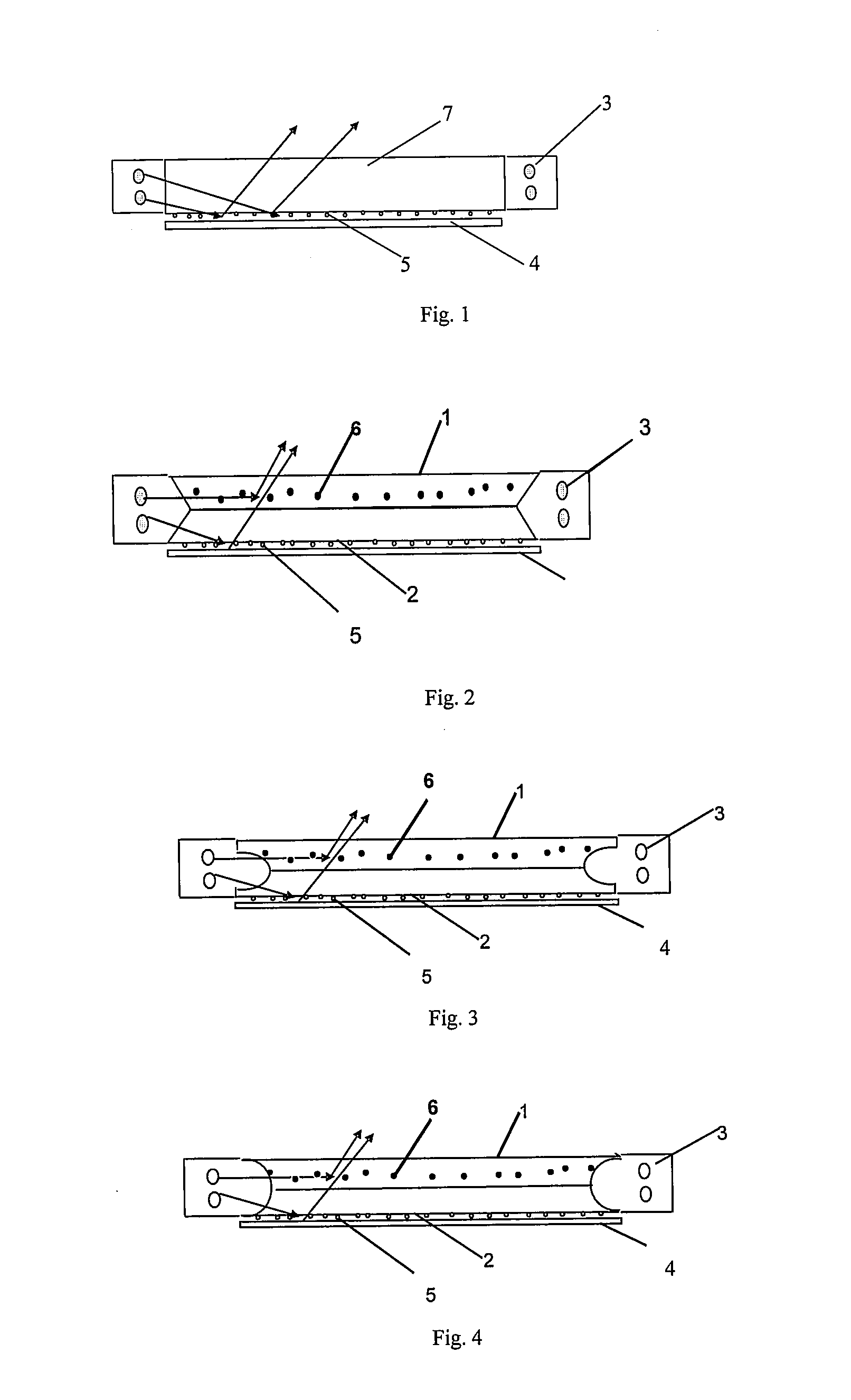
[0020]FIG. 2 is a schematic view showing a backlight module according to a first embodiment of the invention. According to FIG. 2, the backlight module according to the present embodiment comprises at least one light source 3, a light guide plate assembly comprising two light guide plates such as an upper light guide plate 1 and a lower light guide plate 2 that are stacked together, and a reflection film 4 and other optical films as necessary (not shown). The reflection film 4 is disposed below the light guide plate assembly such that the lower surface of the lower light guide plate 2 face the reflection film 4. The light source 3 is disposed on one side or both sides of the light guide plate assembly facing the incident light surface of the light guide plate assembly. The lower surface of the lower light guide plate 2 is constructed with a plurality of concave or convex microstructures 5. Both surfaces of the upper light guide plate 1 may be free of such microstructures, and the up...

second embodiment

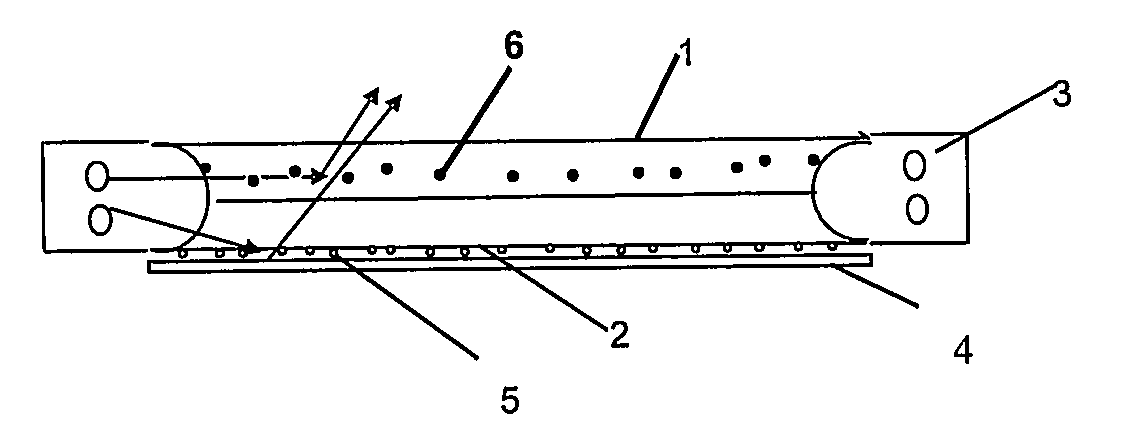
[0026]FIG. 3 is a schematic view showing a backlight module according to a second embodiment of the invention. As shown in FIG. 3, the light guiding plate according to the present embodiment is substantially the same as the one according to the first embodiment except that the incident surfaces of the lower guiding plate 1 and the lower guide plate 2 are formed as a “U” shape structure. Therefore, the detailed description thereof is not repeated herein.

third embodiment

[0027]FIG. 4 is a schematic view showing a backlight module according to a third embodiment of the invention. As shown in FIG. 4, the light guide plate according to the present embodiment is substantially the same as the one according to the first embodiment except that the incident surfaces of the lower guide plate 1 and the lower guide plate 2 are formed as a semi-circle shape structure. Therefore, the detailed description thereof is not repeated herein.

[0028]The incident surface of the light guiding assembly can be further changed as necessary, such as an irregular arc shape.

[0029]Since the light diffusing particles in the upper light guide plate can change the direction of the incident light, the light incident into the upper light guide plate can be emitted directly from the upper surface of the light guide plate assembly. The lower surface of the lower light guide plate can also change the direction of the light incident into the lower light guide plate by the concave or conve...


PUM


Abstract

A backlight module is provided, which comprises a light guide plate assembly comprising an upper light guide plate and a lower guide plate that are stacked together, at least one light source and a reflection film. The light source is disposed on at least one side of the light guide plate assembly with a light incident surfaces of the light guide plate assembly facing the light source. The reflection film is disposed below the light guide plate assembly.

Description

FIELD OF THE INVENTION[0001]The present invention relates to a backlight module of a liquid crystal display (LCD).BACKGROUND OF THE INVENTION[0002]One of the most important components in a backlight module of a liquid crystal display is a light guide plate. FIG. 1 is a schematic view showing a conventional side-type (edge illustration) backlight module without an optical film(s). As shown in FIG. 1, the basic structure of the conventional backlight module comprises one or more light sources 3, a reflection film 4, a light guide plate 7 and a plurality of optical films (not shown) such as a diffusion film, a prism film and a protection film which can be combined in various ways as necessary. The brightness of the backlight module is typically enhanced by the prism film; however, the prism film is expensive and also suffers from inevitable defects during its operation. For example, the prism film tends to warp when heated, and the prisms thereon tend to be scratched, which gives rise ...

Claims


Application Information

Patent Timeline
Patent Type & Authority Applications(United States)
IPC IPC(8): F21V7/04
CPCG02B6/0041G02B6/0043G02B6/0055G02F1/1335
Inventor ZHENG, XIAOPAN
Owner BEIJING BOE OPTOELECTRONCIS TECH CO LTD
Why Eureka
Try Eureka