Air Gap Servo for Optical Recording

a technology of optical recording and air gap, which is applied in the direction of data recording, instruments, and disposition/mounting of heads, etc., can solve the problems of only available air gap error signals, slow pull-in procedure, and crash of head-discs, and achieve the effect of low risk of head-disc crash

Inactive Publication Date: 2008-10-30
KONINKLIJKE PHILIPS ELECTRONICS NV
View PDF6 Cites 9 Cited by
  • Summary
  • Abstract
  • Description
  • Claims
  • Application Information

AI Technical Summary

Benefits of technology

[0005]Therefore it is an object of the invention to provide an air gap servo system and p

Problems solved by technology

Hence, during the pull-in procedure overshoot may pose a severe problem, eventually resulting in a head-disc crash if the head comes into contact with the disc surface.
However, the air gap error signal is only avail

Method used


Image

  • Air Gap Servo for Optical Recording
  • Air Gap Servo for Optical Recording
  • Air Gap Servo for Optical Recording

Examples


Embodiment Construction

[0029]An optical recording system using a near field optical head, which consists of an aspherical lens and a Solid Immersion Lens (SIL), has been proposed as a technology to read out 50 Gbyte or more on a 12 cm optical disc. In this system, it is essential to maintain an air gap between the SIL bottom surface and the disc constantly in a near field position where the evanescent wave is detectable. Thereto an air gap servo system is required

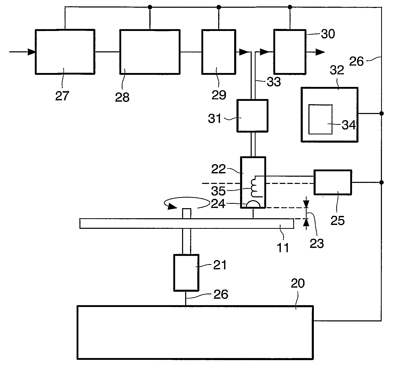
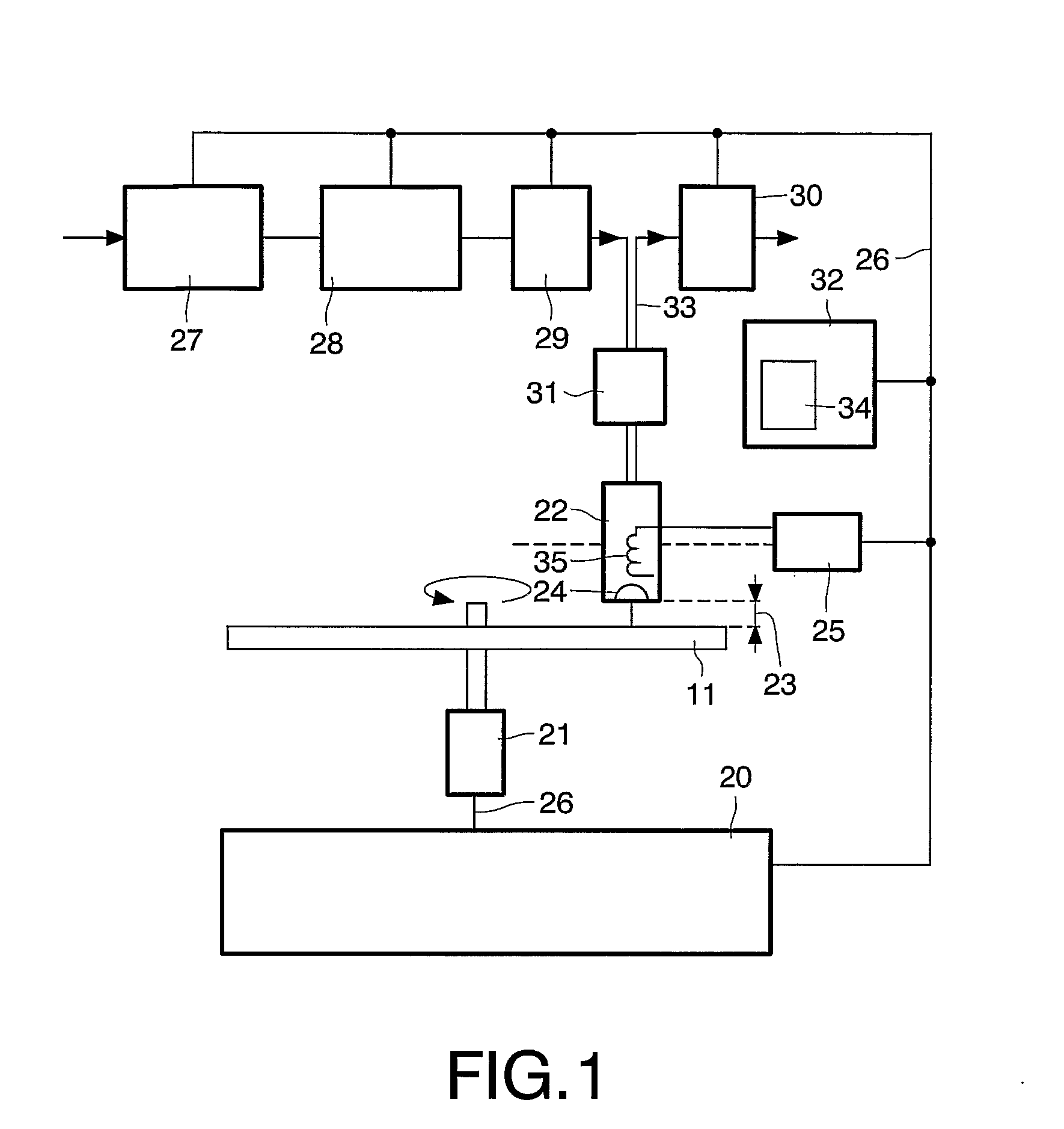
[0030]FIG. 1 shows an optical recording device having an air gap servo. The device is for optically reading and / or recording data on a record carrier 11 via a near field optical system. The near field optical system is known as such, inter alia from doc[1] and from K. Saito, et. al, “Readout Method for Read Only Memory Signal and Air Gap Control Signal in a Near Field Optical Disc System,” Jpn. J. Appl. Phys. Vol. 41 (2002), pp. 1898-1902 (further referred to as doc[2]). The disc-shaped record carrier 11 has a track 9 arranged as a spiral or annu...


PUM


Abstract

A device reads and/or records marks in a track on a record carrier via near field optical recording. The device has a head including a lens to be positioned at a near field distance from a surface of the record carrier. An air gap controller is for controlling an air gap between the lens and the surface, and has an approach mode for bringing the lens from a remote distance in the far field (72) to the near field distance. Thereto the controller provides an increasing periodical excitation signal (73) for generating a sequence of approach instants (77) at which the lens approaches the surface. At the approach instants the lens has substantially zero velocity (76). The sequence of approach instants brings the lens subsequently closer to the surface. When the lens enters in the near field range (71) at one of the approach instants (77), the air gap controller is switched to closed loop mode.

Description

FIELD OF THE INVENTION[0001]The invention relates to a device for near field optical recording, information being represented by marks in a track on a record carrier, the device comprising a head including a lens to be positioned by a lens actuator at a near field distance from a surface of the record carrier for generating a scanning spot on the track.[0002]The invention further relates to a pull-in method for bringing a lens from a remote distance to a near field distance from a surface of a record carrier for use in near field optical recording, information being represented by marks in a track on the record carrier to be scanned via a head including the lens.BACKGROUND OF THE INVENTION[0003]An air gap servo for near-field optical recording is known from the document “Gap Servo System for a Biaxial Device Using an Optical Gap Signal in a Near Field Readout System,” by T. Ishimoto, K. Saito, T. Kondo, A. Nakaoki and M. Yamamoto, published at ISOM / ODS 2002 (further referred to as d...

Claims


Application Information

Patent Timeline
IPC IPC(8): G11B7/00G11B7/09G11B7/135
CPCG11B7/1387G11B7/08511G11B7/085G11B7/09
Inventor LEE, JUILZIJP, FERRY
Owner KONINKLIJKE PHILIPS ELECTRONICS NV
Why Eureka
Try Eureka