Drill rig apparatuses with directly driven shaft & drilling fluid pump systems

a technology of drilling fluid pump and shaft drive, which is applied in the direction of positive displacement liquid engine, reciprocating combination engine, piston pump, etc., can solve the problems of large drive system, relatively large mud pump system, and relatively complex known mud pump and mud pump system, so as to reduce the overall size and space requirements, increase the efficiencies, and reduce the inefficiencies.

Inactive Publication Date: 2008-10-30
VARCO I P INC
View PDF18 Cites 48 Cited by
  • Summary
  • Abstract
  • Description
  • Claims
  • Application Information

AI Technical Summary

Benefits of technology

[0009]The present invention discloses, in certain aspects, a fluid pumping system, also known as a mud pump system (in certain particular aspects a drilling fluid pumping system), for pumping fluid (e.g., but not limited to, drilling fluid or mud used in wellbore operations). In certain aspects an AC motor (or motors) operates a pump apparatus to pump the fluid. In certain aspects of systems according to the present invention in which one or more AC (alternating current) motors applies power directly, increased efficiencies are possible, inefficiencies associated with non-direct drive systems are eliminated, overall size and space requirements are reduced, and / or overall system weight is reduced.

Problems solved by technology

Certain prior, known mud pumps and mud pump systems have relatively complex, relatively large, and relatively heavy drive systems with typical connecting rods, eccentric shafts, belts, pulleys, chains and sprockets, gears and / or other speed reduction apparatus.

Method used


Image

  • Drill rig apparatuses with directly driven shaft & drilling fluid pump systems
  • Drill rig apparatuses with directly driven shaft & drilling fluid pump systems
  • Drill rig apparatuses with directly driven shaft & drilling fluid pump systems

Examples


Embodiment Construction

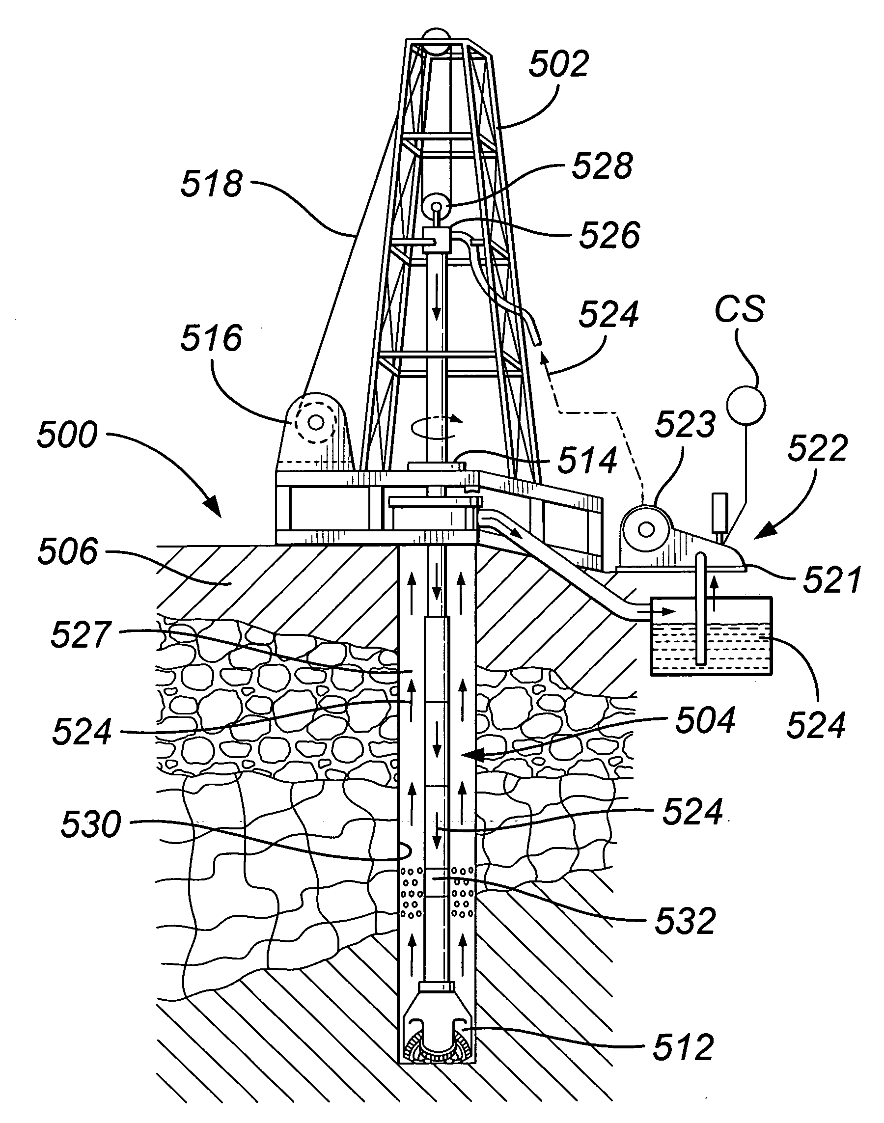
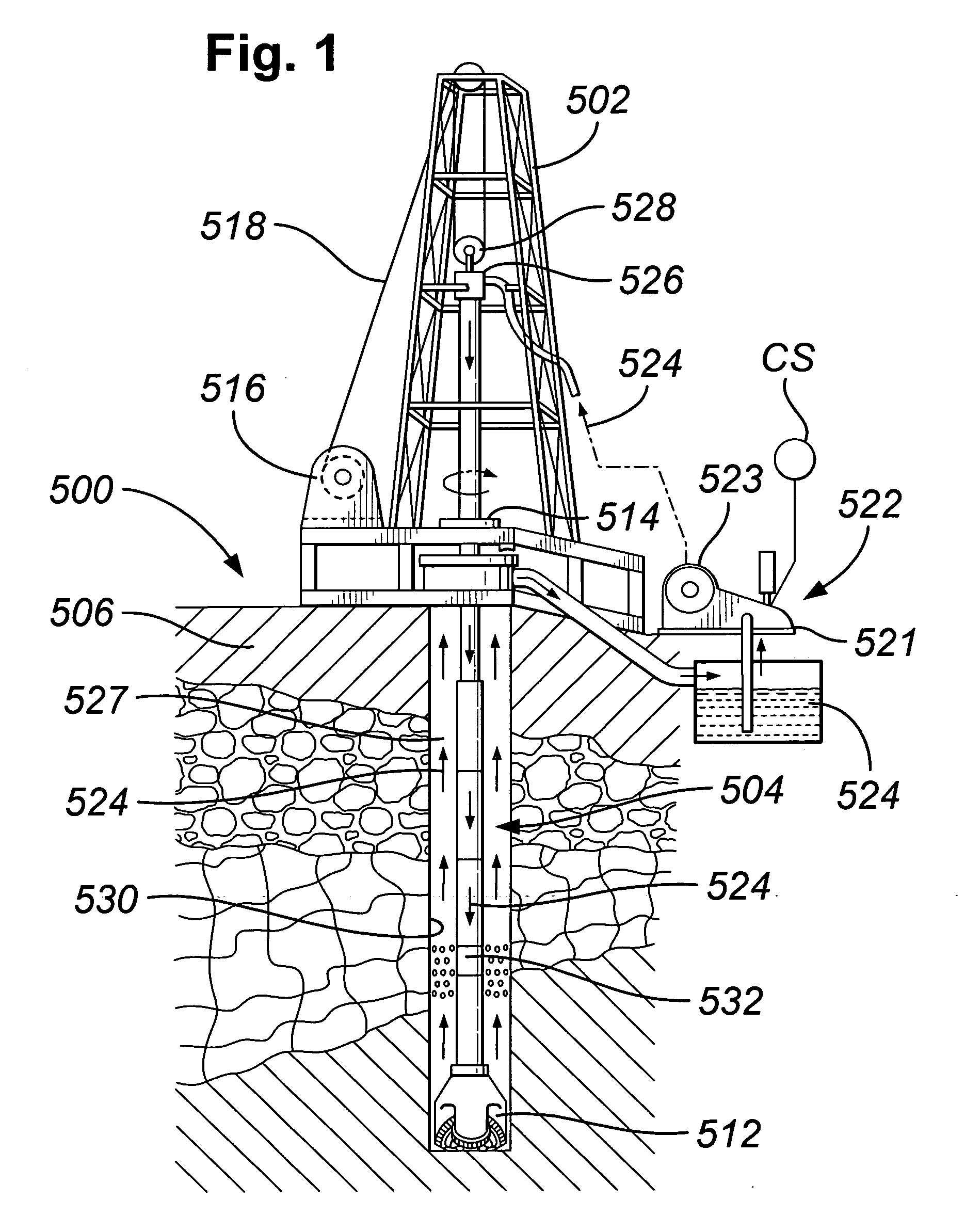
[0035]The system 500 shown in FIG. 1 includes a derrick 502 from which extends a drillstring 504 into the earth 506. The drillstring 504, as is well known, can include drill pipes and drill collars. A drill bit 512 is at the end of the drillstring. A rotary system 514, top drive system 526, and / or a downhole motor 532 (“fluid motor”, “mud motor”) may be used to rotate the drillstring 504 and the drill bit 512. A typical drawworks 516 has a cable or rope apparatus 518 for supporting items in the derrick 502. A mud pump system 522 with one, two, three-to-ten, or more mud pumps 521 according to the present invention supplies drilling fluid 524 to the drillstring 504. Drilling forms a wellbore 530 extending down into the earth 506. Each mud pump system 521 has at least one AC motor 523 directly connected to a main drive pinion shaft of the pump system (any disclosed herein for systems according to the present invention). In certain aspects, the system 522 has two such motors, one on eac...


PUM


Abstract

A drilling rig system with a main shaft or shaft-like structure driven directly by an AC motor; the system in one aspect for pumping fluid (e.g., but not limited to, drilling fluid), the system having, in certain aspects, pump apparatus with a pumping section and a motor section, the pumping section having an inlet and an outlet, the motor section having a drive shaft for connection to a pump pinion shaft for reciprocating in and out of the pumping section to alternately suck fluid into the inlet and pump fluid out the outlet, and the motor being directly connected to the pump pinion shaft, and methods for using such a system.

Description

BACKGROUND OF THE INVENTION[0001]1. Field of the Invention[0002]This invention is directed to: drill rig apparatuses (machines, devices, apparatuses, systems) with a driven shaft driven by an AC motor directly connected to the driven shaft without the use of intermediate gear reductions or torque multipliers; drilling fluid pump systems used in drilling wellbores in the earth; and to methods of the use of such apparatuses and systems.[0003]2. Description of Related Art[0004]A wide variety of drilling systems, apparatuses, and methods are disclosed in prior developments including, but not limited to, the disclosures in U.S. Pat. Nos. 6,944,547; 6,918,453; 6,802,378; 6,050,348; 5,465,799; 4,995,465; 4,854,397; and 3,658,138, all incorporated fully herein for all purposes. Prior developments include a wide variety of drilling systems, apparatuses, machines and devices which use a powered shaft driven by a motor with an intermediate apparatus between the motor and the powered shaft such...

Claims


Application Information

Patent Timeline
Patent Type & Authority Applications(United States)
IPC IPC(8): F01B21/00
CPCF04B9/02F04B15/02F04B17/03H02K7/14H02K21/24
Inventor CERVENKA, GREGORY PAULURQUHART, RICHARD
Owner VARCO I P INC
Why Eureka
Try Eureka