
Electronic control system for controlling plant temperature

a technology of electronic control system and plant temperature, which is applied in the direction of electrical control, exhaust treatment electric control, instruments, etc., can solve the problems of inability to allow the responsivity of the down-stream treatment device to reach a level, the temperature range in which the down-stream treatment device can satisfactorily work is limited, and the effect of accurate agreemen

Inactive Publication Date: 2008-10-30
HONDA MOTOR CO LTD
View PDF7 Cites 19 Cited by
  • Summary
  • Abstract
  • Description
  • Claims
  • Application Information

AI Technical Summary

Benefits of technology

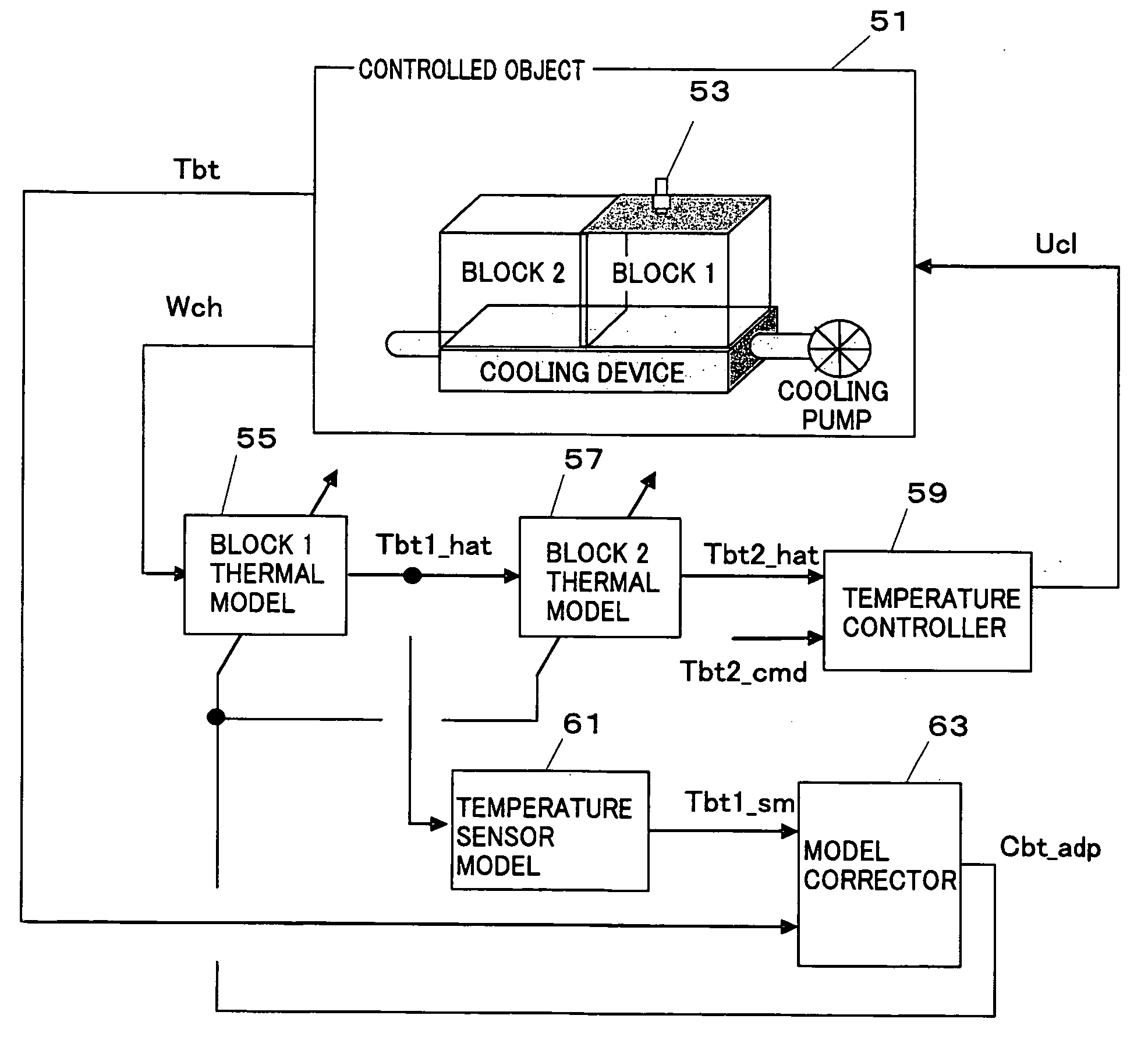
[0013]Even if there are other predetermined parameters (second parameters (Ccat, Cbt)), indicating nonlinear properties relative to predetermined parameters (first parameters (Tcat, Wch)) in the plant and there is a need to control with the parameters the temperature of the plant that changes over time and differs individually from plant to plant, the present invention having the above structure can control the plant temperature to a target value with high accuracy regardless of the time-lag characteristics of the temperature sensor (in the case of exhaust system temperature control). It is also possible to embody an electronic control system that can control the temperature of a part, where the temperature sensor does not exist, of a plant to a target value with high accuracy.
[0022]In yet another embodiment in which the plant is a battery of the present invention, the predetermined first parameter is a parameter (Wch) indicative of an amount of charge to the battery, while the second parameter is a parameter (Cbt) indicative of the exothermic state of the battery. Even if the exothermic properties of the battery vary with age or due to individual variations, the electronic control system of the embodiment can compensate the variations of the properties with the parameters to accurately control the temperature of the battery to be a target value.

Problems solved by technology

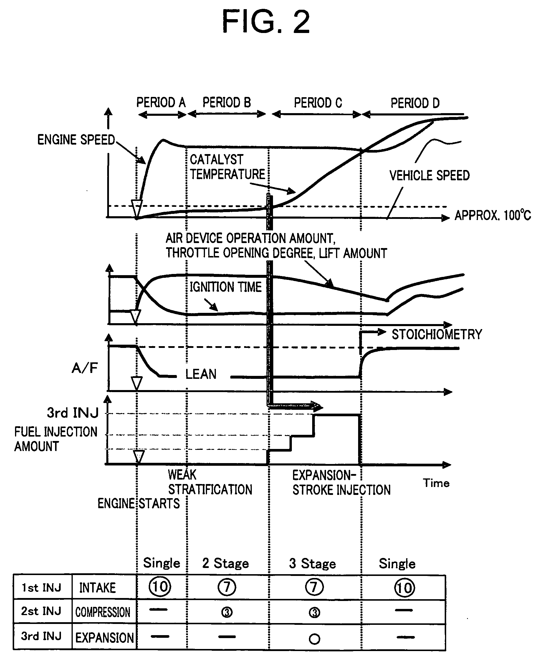
Additionally, lean-burn gasoline engines, auto-ignition combustion engines, variable lift engines, diesel engines and some other engines discharge exhaust gas at low temperatures even after the warm-up of the engines and may not activate their down-stream-treatment devices depending on their operating conditions.
There is another demand for control of the temperature of the down-stream-treatment devices for the reason that the temperature range in which the down-stream-treatment devices can satisfactorily work is limited.
However, the temperature sensor installable on the exhaust system are made to deal with environmental conditions, including temperature difference, corrosive elements (water, sulfuric acid, etc.) and vibration, to which the temperature sensor is exposed, and therefore cannot allow its responsivity to reach a level at which the above-described requirements to control the temperature are fully satisfied.
However, Japanese Patent Application Publication No. 2006-183645 employing a sequential least square method that can correct only the coefficient (constant) of linear models cannot correct nonlinear functions (table and map).
In a case where the temperature of the down-stream-treatment device needs to be increased or decreased in a short period of time (e.g., post-startup rapid warm-up control and regeneration control of diesel's DPF (Diesel Particulate Filter), etc.), the technique in Japanese Patent Application Publication No. 2006-183645 cannot provide adequately accurate model outputs, which may cause an increase of emissions, fuel efficiency degradation and acceleration of down-stream-treatment-device degradation due to excessive rise of temperature.
In addition, the technique in WO 2002 / 070873 achieves only correction of the model's coefficient / constant, and limits the correction timing to a time before the activation of the down-stream-treatment device.

Method used


Image

  • Electronic control system for controlling plant temperature
  • Electronic control system for controlling plant temperature
  • Electronic control system for controlling plant temperature

Examples


Embodiment Construction

1. Conventional Rapid Warm-Up Control for Catalyst

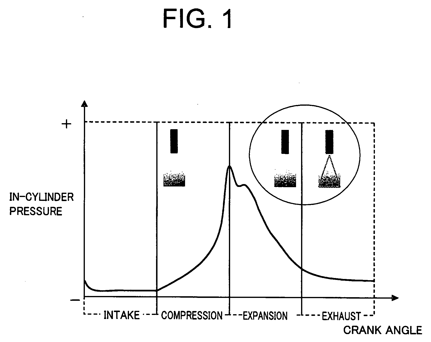
[0055]Widely-used conventional technology for reducing emissions immediately after startup of an engine, as shown in Japanese Patent Laid-Open No. 10-299631 (FIRE), is achieved by reducing the activation time of a catalyst with heat energy of exhaust gas increased (in not only temperature but also mass) by boosting the amount of intake air at a fast idle more than that in a usual idling state and retarding the ignition timing.

[0056]However, exhaust systems (4-2-1 exhaust system, etc.), which are employed for a high-performance engine to attain a high output / high torque, have a great heat dissipation area and heat capacity that absorbs the heat energy of the exhaust gas with an increase in temperature of the exhaust system, thereby reducing the speed of the temperature rise of the catalyst. Because of this, vehicles employing the high-performance engine-compatible exhaust system have a problem to reduce the activation time of the cata...


PUM


Abstract

Nonlinear functions (table and map) of a temperature estimation model are corrected based on outputs from a temperature sensor. An electronic control system calculates, for a plant model constructed to calculate an estimated temperature value of the plant, an estimated temperature value using a correlation model between a first parameter regarding the plant and a second parameter regarding the plant model. This control system controls the temperature of the plant based on the calculated estimated temperature value of the plant. The control system also defines a plurality of functions (Wi) in a range of a plurality of the first parameters for the correlation model, calculates correction coefficients (Kli, Kci) that adjust the height of the plurality of functions based on the output of the temperature sensor and the calculated estimated temperature value of the plant, and corrects the correlation model by the plurality of functions (Wi) and correction coefficients (Kli, Kci).

Description

BACKGROUND OF THE INVENTION[0001]1. Field of the Invention[0002]The present invention relates to a system to electronically control the temperature of a plant.[0003]2. Description of the Related Art[0004]WO 2002 / 070873 describes a device and method for diagnosing internal combustion engines and a control method of the internal combustion engines with the diagnosis device and method, while Japanese Patent Application Publication No. 2006-183645 describes a system for controlling the temperature of a plant that is a controlled object.[0005]The technology in WO 2002 / 070873 features detection of catalyst degradation by defining a model used to estimate the temperature of a catalyst and comparing the output from the model and the output from a temperature sensor installed in the catalyst. When the temperature sensor output indicates a temperature equal to or lower than the light-off temperature of the catalyst, the system corrects the estimated temperature obtained from the model based o...

Claims


Application Information

Patent Timeline
IPC IPC(8): G05D23/00F01N3/18F01N3/24F02D41/06F02D45/00G05B13/00G05B13/04
CPCF01N9/00F01N9/005F01N11/005F02D41/0235F02D2041/1433F02D2200/0802Y02T10/47G05D23/1917H01M10/48H01M10/486H01M10/5004H01M10/5016H01M10/5022G05B13/044H01M10/625H01M10/633H01M10/613Y02T10/40Y02E60/10
Inventor YASUI, YUJIKAWASUMI, IKUE
Owner HONDA MOTOR CO LTD
Learn More