
Cutting tool

a cutting tool and cutting blade technology, applied in the field of cutting tools, can solve the problems of product packaging that is difficult to open safely, plastic packaging, especially for electronic devices, and has undergone substantial changes, and achieves the effect of adding strength to the construction of the tool

Inactive Publication Date: 2008-11-06
PERLMUTTER THOMAS
View PDF12 Cites 23 Cited by
  • Summary
  • Abstract
  • Description
  • Claims
  • Application Information

AI Technical Summary

Benefits of technology

[0007]The angle of the second blade is selected so that the blade will not be in a position to cut the packaging unless the user holds the handle above the packaging. The second cutting blade is placed such that it will cut the packaging only when the handle is held at a 30 degree or greater above the plane of the packaging. The configuration and diagonal placement of the blade at less than 20.5 degrees from the horizontal, and preferably 19.5 degrees, across the opening between the finger and thumb prevents the user from being able to insert his fingers into the slit made in the packaging and subsequently, cut on the plastic.
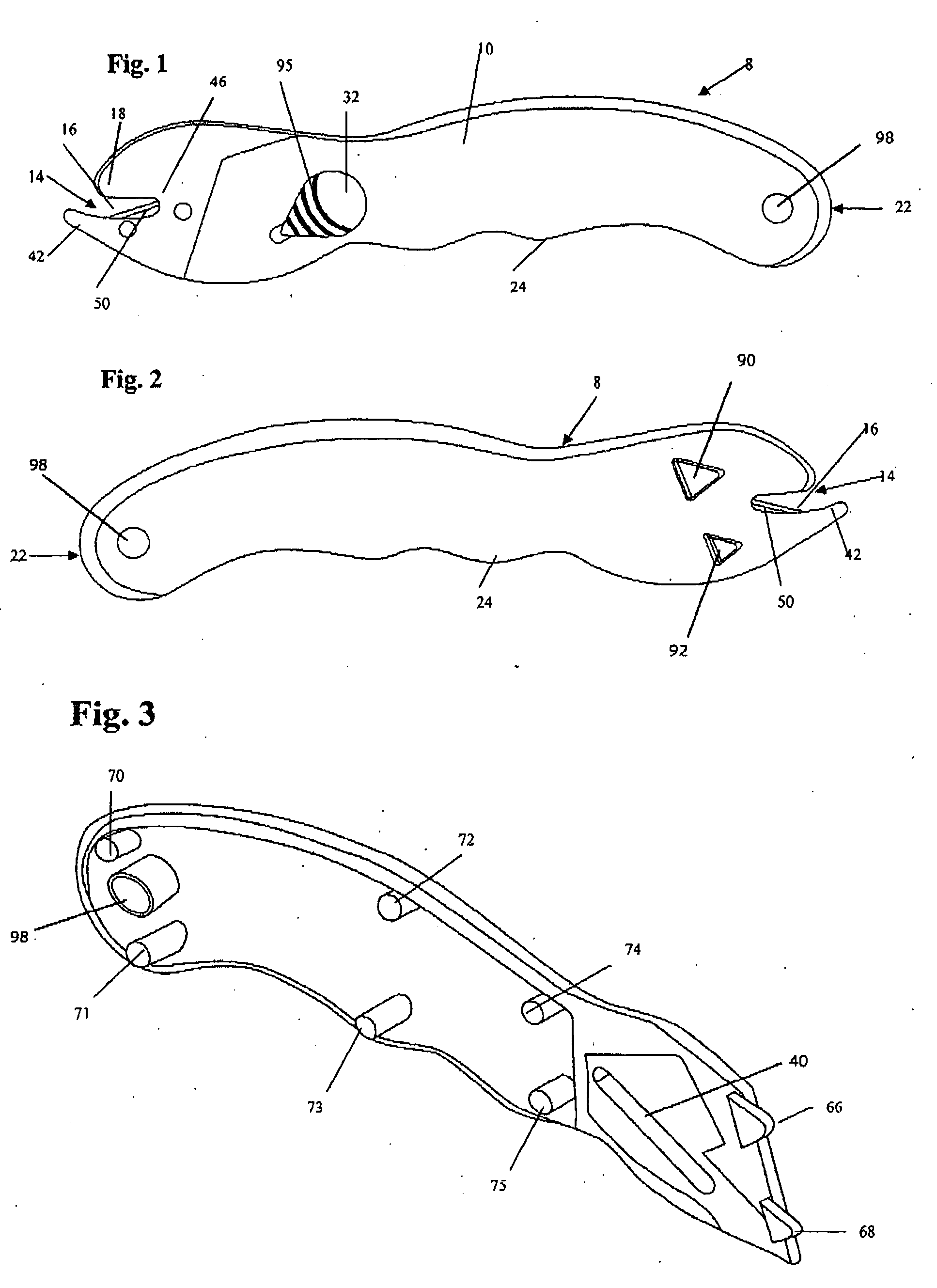
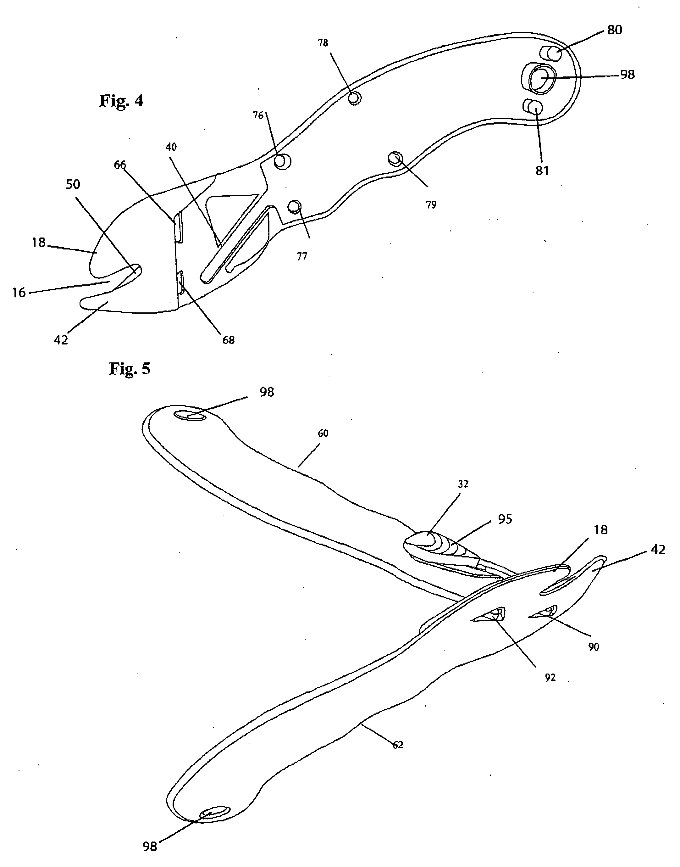
[0008]An interlocking housing assembly is provided to add strength to the construction of the tool. The housing has a front half and a back half, the two halves secured to each other. The inside of the front half of the housing panel is formed with male tabs which are inserted into tab receivers provided on the inside of the back half panel. As the tool is closed, the male tabs are inserted into the tab receivers which lock the front side of the tool to back side of the tool.

Problems solved by technology

Product packaging has undergone substantial change in recent years and has generally become more difficult to remove.
The plastic packaging, especially for electronic devices, is very difficult to open safely.
The heavy plastic resists cutting, and can become very sharp, cutting the unwary consumer.
However, it was discovered that when my cutting tool was used for cutting the heaviest plastic package repeatedly caused the two main sections of the housing to separate.
Further, it was discovered that some injuries were occurring if the tool was used improperly.

Method used


Image

  • Cutting tool
  • Cutting tool
  • Cutting tool

Examples


Embodiment Construction

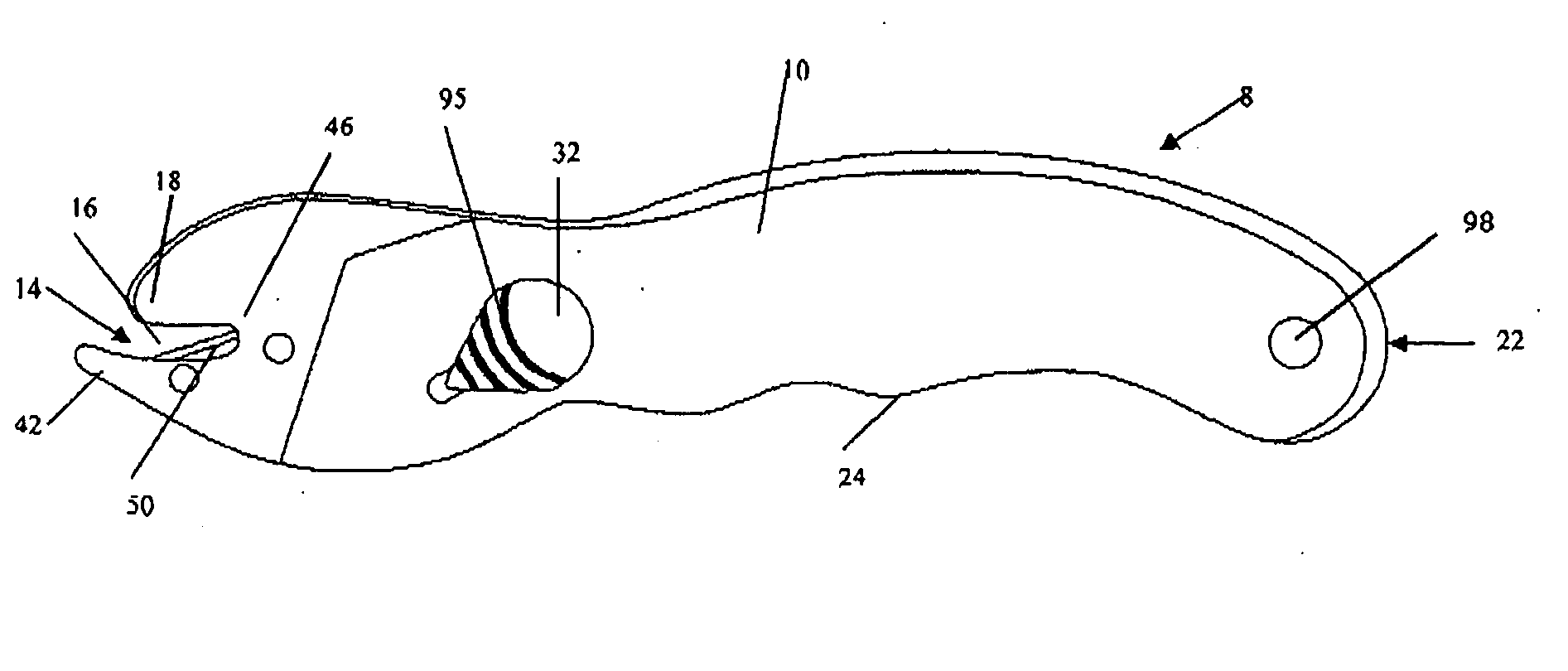
[0020]An assembled cutting tool 8 is shown in FIGS. 1 and 8. The cutting tool includes a housing 10 having a first end 14 and a second end 22. The first end 14 is formed with an elongated finger 42 and a thumb 18 separated by an opening 16. The lower portion of the housing 10 is formed with a grip 24 shaped to fit the fingers of the user's hand.

[0021]The cutting tool further includes a spring-biased first blade 28 shown in FIGS. 8 and 9. First blade 28 has a cutting position with the blade 28 protruding from the housing 10 as shown in FIG. 8 and a retracted position inside the housing 10 as shown in FIG. 1. In the preferred embodiment, a control mechanism which is preferably, a push button 32 moves the first blade 28 from the retracted position to the cutting position.

[0022]The housing forms an elongated finger 42 which extends from the first end 14 of the housing 10 forming a cantilever. The finger 42 is located opposite to the thumb 18 and is formed at the termination of the first...


PUM

PropertyMeasurementUnit
Fractionaaaaaaaaaa
Angleaaaaaaaaaa
Angleaaaaaaaaaa

Abstract

A cutting tool includes a housing having a first end with a first edge and a second end. A handle adapted to receive a hand is formed in the housing. The housing encloses a first blade which has a cutting position when the first blade extends from the housing and a retracted position with the blade inside the housing. An elongated finger portion is extended from the first end of the housing. The finger portion and the first edge define an elongated opening having a junction at the first end of the housing. A second blade is embedded in the housing at the preferred angle of 19.5 percent and diagonally spans the opening and the junction. The second is shaped, sized and orientated to facilitate forward slitting of heavy plastic sheet. The first blade slides axially along an interior track. A biasing means repositions the first blade from the retracted position to the cutting position. The first blade makes a slit in the packaging. The elongated finger is then inserted into the opening and the second blade enlarges the slit to the desired length to remove the item from its packaging.

Description

[0001]This Application claims the benefit pursuant to 35 U.S.C. 119(e) of U.S. Provisional Patent Application Ser. No. 60 / 915,356 filed by the applicant on May 1, 2007.FIELD OF INVENTION[0002]The present invention relates generally to cutting tools and more particularly to a tool for cutting heavy plastic.BACKGROUND OF THE INVENTION[0003]Product packaging has undergone substantial change in recent years and has generally become more difficult to remove. The packaging must withstand the rigors of shipping, impede shop-lifters, and attractively display the product for retail sales and hold the product in a compact container. Increasingly, the packaging material of choice has become plastic. The plastic is formed from heavy clear sheet to conform to the contours of the products and to display the products for the retail sales. The plastic packaging, especially for electronic devices, is very difficult to open safely. The heavy plastic resists cutting, and can become very sharp, cutting...

Claims


Application Information

Patent Timeline
IPC IPC(8): B26B3/06B26D1/00
CPCB26B5/00B26B27/005Y10T83/04
Inventor PERLMUTTER, THOMAS
Owner PERLMUTTER THOMAS
Learn More