Railway Wagon

Inactive Publication Date: 2008-11-06
FLEXIWAGGON
View PDF23 Cites 16 Cited by
  • Summary
  • Abstract
  • Description
  • Claims
  • Application Information

AI Technical Summary

Benefits of technology

[0009]The combination of the displacing, tilt-preventing and supporting devices results in a wide range of application. Thus, it is for instance possible first to displace the load carrier a distance and then drive the abutment device of the supporting device down to abut against the ground by the side of a rail. During the first movement, which is driven by the displacing device, and/or later during the displacement, the tilt-preventing device counteracts any tilting tendencies of the load carrier. With the abutment device driven down, the load carrier can, in a very reliable manner, be further displaced to the position where loading/unloading is to occur. If the ground is relatively soft, the sliding member ensures that the abutment device slides on top or in any case at such a high level that a continued displacement is allowed. Of course, there is a dependence on the location of the abutment device seen in the lateral direction of the load carrier and a relationship between that location and how great initial displacement can be performed. However, it is easy to understand that the means defined in the claim are sufficient to carry out such a solution.
[0010]In one embodiment of the railway wagon according to the invention, each abutment device further comprises a supporting wheel, a portion of the supporting wheel at least in the extended position extending below an underside of the sliding member. In another embodiment, the supporting wheel is adjustable so that in said extended position it can also be located in a position where it does not extend below the underside of the sliding member. The combination of supporting wheel and sliding member is advantageous since the friction against the base is minimised for all types of base. If the base is hard and the supporting wheel extends below the underside of the sliding member, it will roll on the base while the sliding member is freely suspended. If, however, the base is so soft that the supporting wheel sinks down, the sliding member takes up some of, or the entire, load and slides on the base. This means that the friction will be reduced, compared with a wheel digging itself deep down into the base. With varying bases, the embodiment with the adjustable supporting wheel has the advantage that it is possible to choose whether the supporting wheel is to be used or not. As will be evident from additional embodiments, it is within the scope of the invention to use a plurality of sliding members and/or a plurality of supporting wheels in various configurations to achieve optimum applicability. Moreover, as is also defined in one embodiment, the sliding member is advantageously ski-shaped, in which case its end curving upwards allows it to manage soft bas

Problems solved by technology

A problem with this construction of the supporting device is that it requires a solid and substantially flat base in order to function in a satisfactory manner.
Moreover such a construction is relatively complex.
Drawbacks of this railway wagon are on the other hand that

Method used


Image

  • Railway Wagon
  • Railway Wagon
  • Railway Wagon

Examples


Embodiment Construction

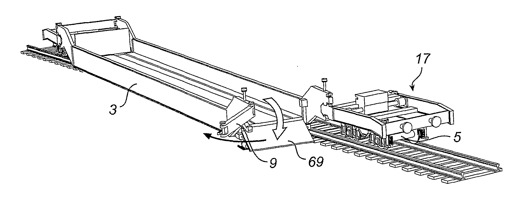
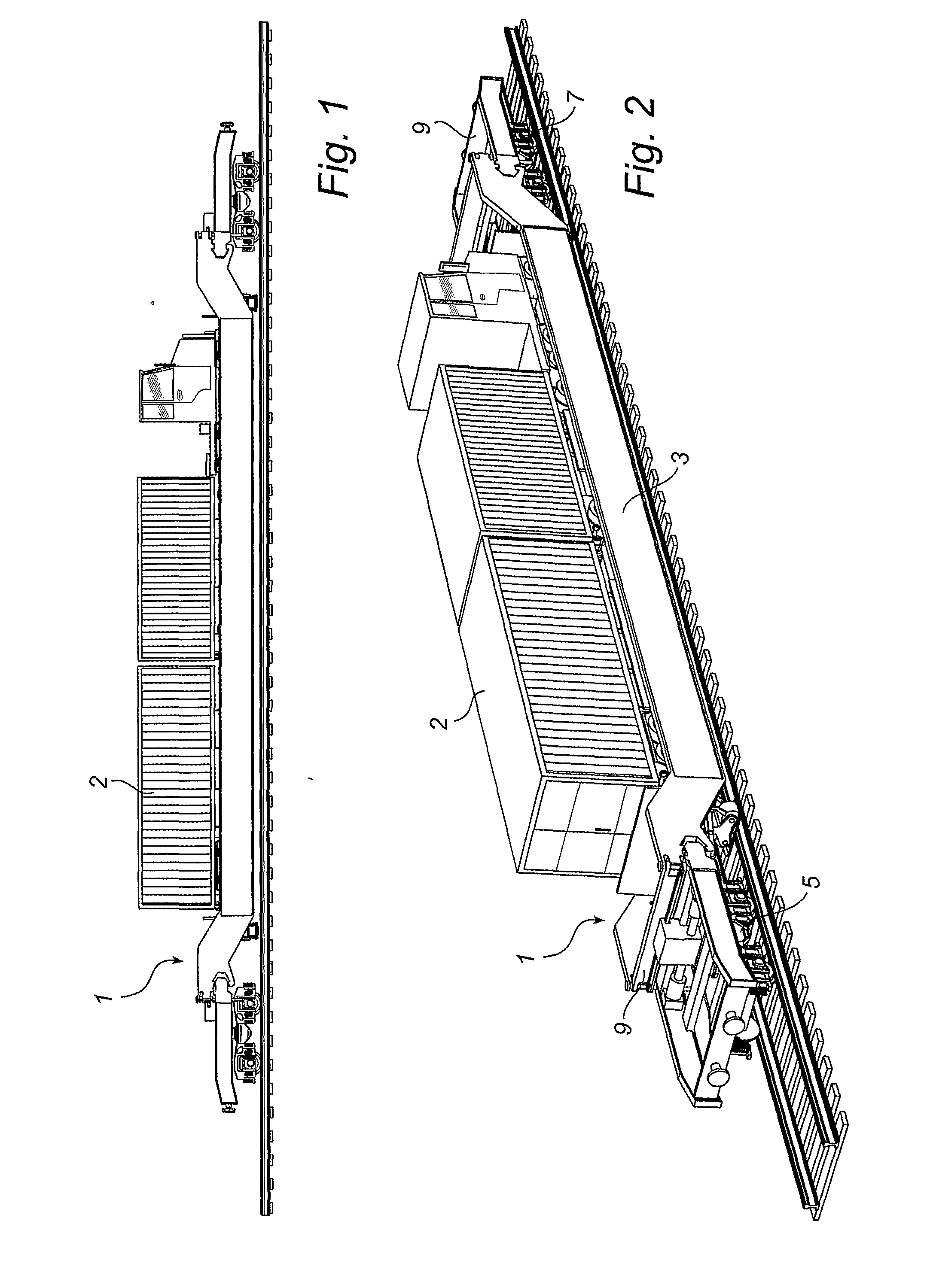
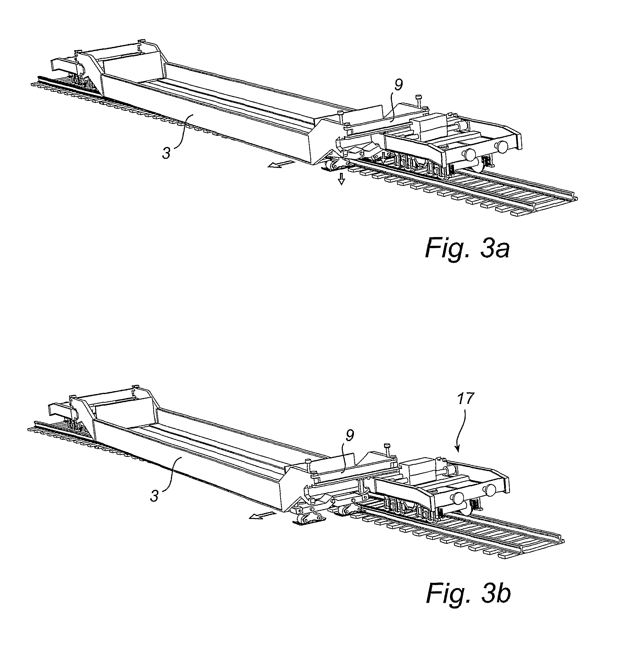
[0022]The invention concerns a railway wagon which is designed for the modern concept of loading and unloading of entire vehicles. FIGS. 1 and 2 illustrate precisely a railway wagon 1 which carries a truck 2. FIG. 2 shows the principle of construction which enables the concept. The railway wagon comprises a load carrier 3, which is releasably connected to front and rear bogies 5, 7. When loading of a vehicle, for instance a truck, is to occur, one / the front end of the load carrier 3 is released and displaced, in this case by being pivoted on a pivot which is positioned at its other / rear end, relative to the bogie 3. A crossbar 9, which is included in a tilt-preventing device which will be described in more detail below, is released at its one end and pivoted away. Then the vehicle can drive up on the load carrier 3, after which the load carrier is returned to the initial position and locked. FIG. 14 shows that the other end of the load carrier 3 can also be pivoted outwards in a cor...


PUM


Abstract

The present invention relates to a railway wagon comprising a load carrier and front and rear bogies. The load carrier is releasably connected to, and laterally displaceable in relation to, the respective bogies. Supporting devices are mounted at the ends of the load carrier. They support the load carrier when it is displaced in relation to the bogie. Each supporting device comprises an abutment device which is vertically operable between a pulled-up position and an extended position. At each end of the load carrier there is also a displacing driving device for displacing the load carrier relative to the bogie, and a device that counteracts tilting tendencies of the load carrier. Each abutment device comprises a sliding member, which can slide on the base in the extended position. The railway wagon can thus be displaced, for instance pivoted outwards at one end, to allow a truck to be driven on to or off the same.

Description

FIELD OF THE INVENTION[0001]The present invention relates to a railway wagon comprising a load carrier and front and rear bogies, the load carrier having front and rear ends, at which the load carrier is releasably connected to the respective bogies, the load carrier being at each end laterally displaceable in relation to the bogie, and the load carrier being provided at each end with a supporting device, which supports the end of the load carrier in a position where it is displaced in relation to the bogie.BACKGROUND ART[0002]A previously known railway wagon having the features defined by way of introduction is disclosed in the publication WO 96 / 11829.[0003]When the load carrier is released from the bogie at one or both ends to be displaced to a loading and unloading position, a supporting device is driven down right between the railway rails to abut against the base. The supporting device comprises a driving wheel, which performs the displacement, and two supporting wheels, which ...

Claims


Application Information

Patent Timeline
IPC IPC(8): B61D47/00B61DB61D3/18
CPCB61D47/005B61D3/184B61D3/182
Inventor ERIKSSON, JAN
Owner FLEXIWAGGON
Why Eureka
Try Eureka