Coal fired process heaters

a technology of process heaters and coal, which is applied in the direction of lighting and heating apparatus, solid fuel combustion, combustion types, etc., can solve the problems of pulverized coal, insufficient operation of conventional heaters designed for gas or oil firing, and refractory surfaces exposed to hot flue gas, etc., to reduce the risk of corrosion, and reduce the effect of interaction

Inactive Publication Date: 2008-11-06
CROSS ALAN
View PDF12 Cites 10 Cited by
  • Summary
  • Abstract
  • Description
  • Claims
  • Application Information

AI Technical Summary

Benefits of technology

[0003]This invention relates to the design of coal fired process heaters. These heaters consist of a radiant section, a convection section, a radiant section process coil, a convection section process or heat conservation coil, one or more burners, one or more centrifugal gas-solids separators, a water-steam cooled solids containment hopper, a solids removal system, and radiant and convection coil steam jet rotary soot blowers. The radiant section is provided with a contiguous helical tubular coil or a contiguous vertical tube serpentine coil, which shields the refractory from hot flue gas and molten ash particulates that could otherwise cause excessive fouling and heater inoperability. In the case of FIG. 1, one or more burners, firing down words and in the case of FIG. 4 horizontally, are designed such that combustion occurs only after the premixed air-fuel mixture leaves the burner. Burners are sized so that the fuel-air mixture exiting the burner does so at a velocity of 125 feet per second. Thru use of a firebox height to width ratio of 2.8, the width being measured diametrically between helical coil centerlines as in the case of FIGS. 1 and 6, or the center line distance between tubes at the wall, in the case of FIG. 4, there is assurance that there will be but little contact between the diverging flue gas jets and tubes at the wall of the enclosure except at the flue gas heater outlet at the top or bottom of the heater radiant section. In the case of FIG. 6, an orifice is provided at the radiant section flue gas inlet of the vertically oriented helical coil heater, located immediately above the outlet of the traveling grate stoker. This orifice is sized to provide for a hot flue gas velocity of 250 feet per second. As in the case of FIG. 1, there should be but slight interaction between the hot flue gas jet and the tubes at the wall of the heater, except at the heater outlet. Tubes of which the heating surfaces are comprised are of Incoloy Alloy 800H, a high chrome nickel alloy, which is considered adequately resistant to corrosion by molten fly ash, particularly since the arrangement of the heating surface-burner arrangements in the designs proposed are such as to limit interaction between burner generated fly ash and heat transfer surfaces. Corrosion is also minimized due to the low operating temperature of tube wall surfaces relative to the fusion temperature of the ash.
[0004]Gas-solids centrifugal separators are provided to accept flue gases, laden with solidified ash particulates from the radiant section outlet, and discharge the gases, very nearly devoid of particulates, to the convection section. The cleanliness of flue gas entering the convection section which results, permits the use of conventional convection section heating surfaces such as bare and / or finned tubes on closely spaced triangular or quadrilateral centers. Efficient operation of the radiant and convection heating surfaces is also maintained thru use of rotary soot blowers, which use high pressure steam as a blowing medium. Ash solids removed from the tubes by soot blower action are captured by a water-steam cooled ash containment hopper which conveys the ash solids to an outlet system consisting of rotary valves and pneumatic conveying nozzles. In those instances where movement of ash from the hopper outlet to one or more remote outlet nozzles is necessary, use is made of screw conveyors upstream of the rotary valves and pneumatic conveying nozzles. A steam drum is provided to separate steam and hopper coolant and allow for movement of coolant thru the hopper by means of natural or forced circulation.

Problems solved by technology

In some instances the coils are fired from both sides, but invariably refractory surfaces exposed to hot flue gas are present.
As a result, conventional heaters designed for gas or oil firing, when fired by pulverized coal, do not operate satisfactorily, because the refractories in some instances operate at temperatures above the ash fusion point, allowing molten ash particulates generated by the burning coal to rapidly accumulate on such surfaces, causing heater inoperability and forced shutdown.
Impingement of molten ash on cold surfaces also poses operability and tube corrosion problems that need be considered when firing coal.

Method used


Image

  • Coal fired process heaters
  • Coal fired process heaters
  • Coal fired process heaters

Examples


second embodiment

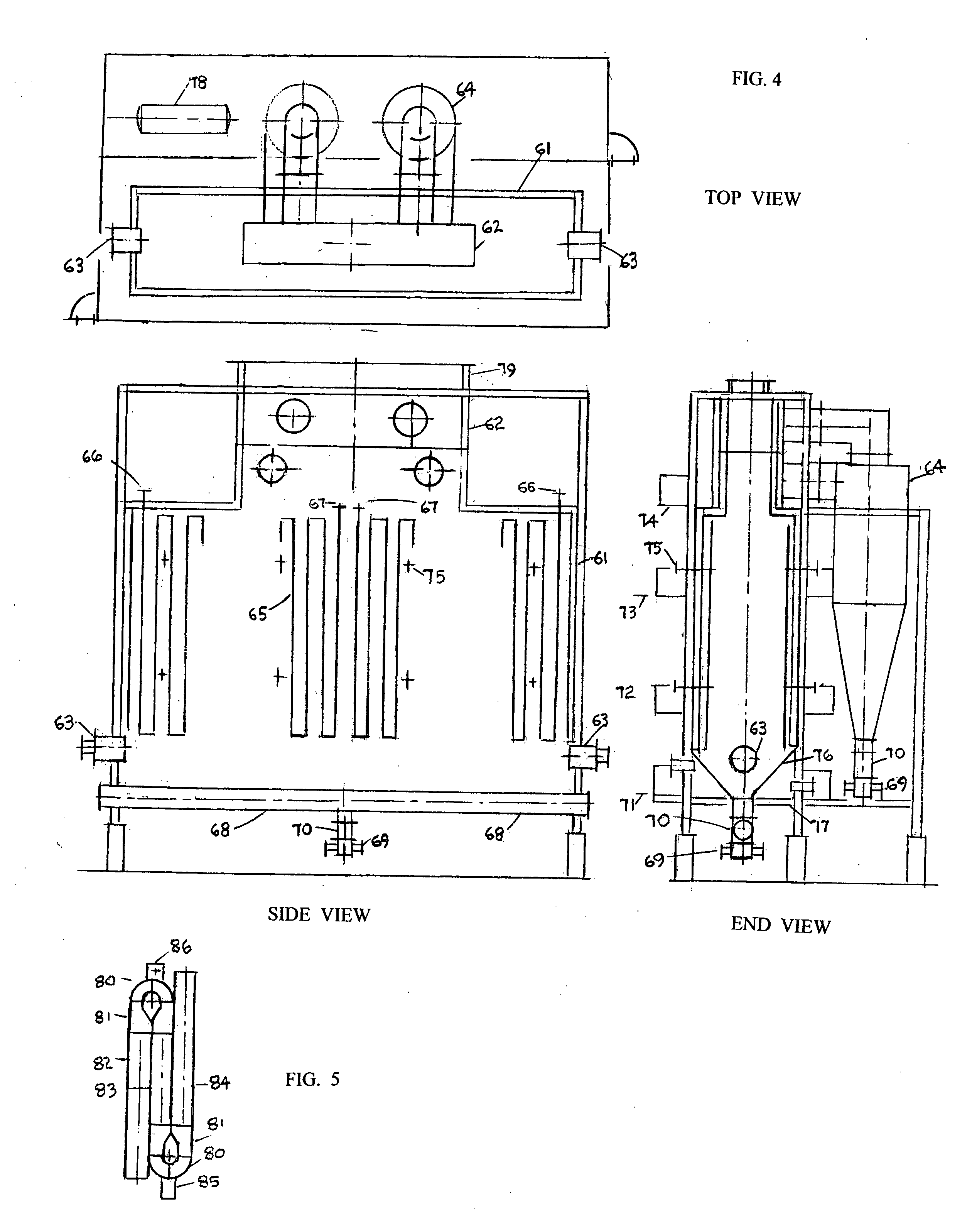
[0021]the proposed invention is as shown in FIG. 4, and consists of a steel shelled enclosure with rectangular side walls, end walls, and top and bottom closures, lined with refractory. A vertical contiguous top supported, bottom guided serpentine tubular coil, 65, is located concentrically with respect to the refractory lined end and side walls of the heater shell, the lining providing backup insulation for the tubular coil. Process fluid, the fluid to be heated, enters the process coils at nozzles, 66, and exits at nozzles 67. The process coil is contiguous so that contact with and fouling of refractory with ash is avoided. By using a serpentine coil arrangement, the process inlet may be located where flue gas temperatures are highest, that is, close to the burner outlets and process coil outlets may be located where flue gas temperatures are lowest, that is, remote from the burner outlets. In so doing, tube metal temperatures are minimized. By providing adequate clearance between...

third embodiment

[0028]the proposed invention is as shown in FIG. 6 and consists of a vertical cylindrical, helical coil radiant section, 118, the vertical shell of which is lined with refractory. A contiguous, up flow, bottom supported, tubular helical coil, 109, is concentrically located with respect to the refractory lining and steel shell, the lining providing back up insulation for the tubular coil. Process fluid, the fluid which is to be heated, enters the process coil at the lower most tube or tubes in the helix, 119, and leaves at the upper most tube or tubes in the helix, 120. The process coil is contiguous, so that contact with, and fouling of the refractories by molten or solidified ash particles cannot occur. By using an up flow process coil arrangement, the process fluid enters at the lower most tubes, 119, at a point where flue gas temperatures are highest and leave at the uppermost tubes, 120, at a point where flue gas temperatures are lowest As a result, overheating of tubes and proc...


PUM

PropertyMeasurementUnit
velocityaaaaaaaaaa
gas velocityaaaaaaaaaa
diameteraaaaaaaaaa

Abstract

One embodiment of the invention consists of a vertical cylindrical process heater with an overhead convection section, a radiant section containing a contiguous, helical, down flow, tubular radiant coil, and one or more top, downward fired, pulverized coal burners. A second embodiment consists of a cabin type heater having a radiant section of rectangular cross section, a contiguous vertical tube serpentine coil, an overhead convection section, and one or more bottom, horizontally fired, pulverized coal, end wall burners. A third embodiment consists of a process heater with a radiant section and overhead convection section, the radiant section having a vertical cylindrical, contiguous, helical, down-flow tubular coil, contained in a refractory lined enclosure of square cross-section. A continuous chain grate coal stoker is provided at the base of the radiant section. A coarse coal feed with a minimum of fines is fed thru a hopper located at one end of the traveling chain grate and essentially coal free ash is removed at the opposite end of the chain grate, thru a nozzle provided with a water seal. One or more centrifugal solids-gas separators are provided at the radiant section flue gas outlets in the case of all three embodiments, for the purpose of removing ash particulates from the flue gas streams, before the latter enter the overhead convection sections. Since the flue gas enters the convection sections very nearly devoid of particulates, the convection sections may be of conventional design utilizing bare and/or finned tubes on closely spaced equilateral or quadrilateral centers.

Description

BACKGROUND OF THE INVENTION[0001]Conventional process heaters find wide usage in oil refineries and chemical plants and are usually fired by oil or gas. Such heaters usually consist of a refractory lined combustion chamber, fired by one or more burners, and are provided with tubular heating elements disposed within the combustion chamber. These elements consist of serpentine coils composed of vertical or horizontal tubes, spaced two or three tube diameters apart, with empty spaces in between, these allowing the back up refractory to be exposed to hot flue gas. In some instances the coils are fired from both sides, but invariably refractory surfaces exposed to hot flue gas are present. As a result, conventional heaters designed for gas or oil firing, when fired by pulverized coal, do not operate satisfactorily, because the refractories in some instances operate at temperatures above the ash fusion point, allowing molten ash particulates generated by the burning coal to rapidly accumu...

Claims


Application Information

Patent Timeline
Patent Type & Authority Applications(United States)
IPC IPC(8): F23D1/00B21D47/00
CPCF23J3/00F23J3/04Y10T29/49616F23J15/027F23J9/00
Inventor CROSS, ALAN
Owner CROSS ALAN
Why Eureka
Try Eureka