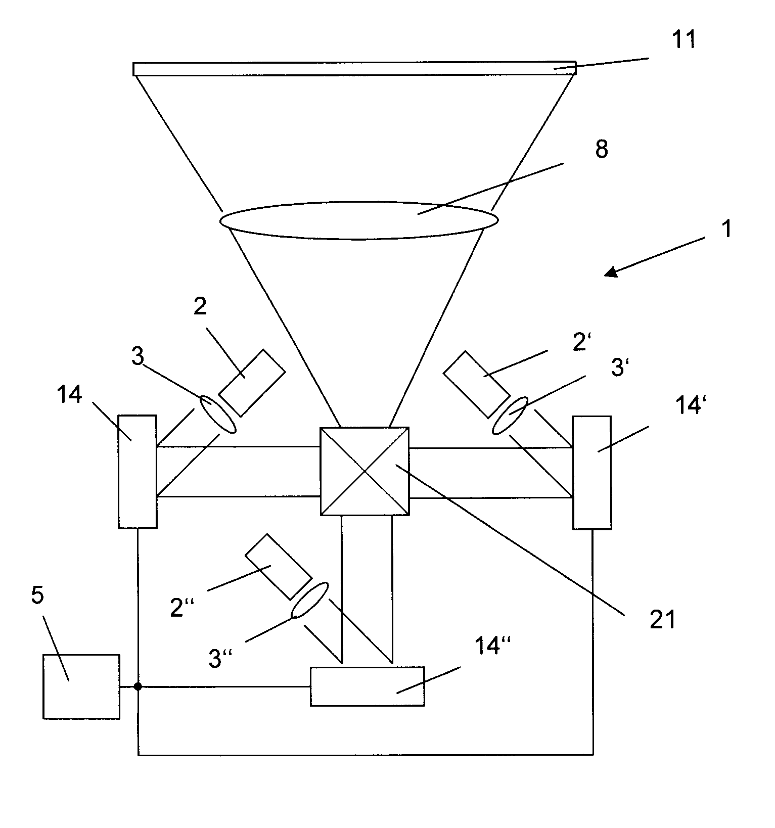
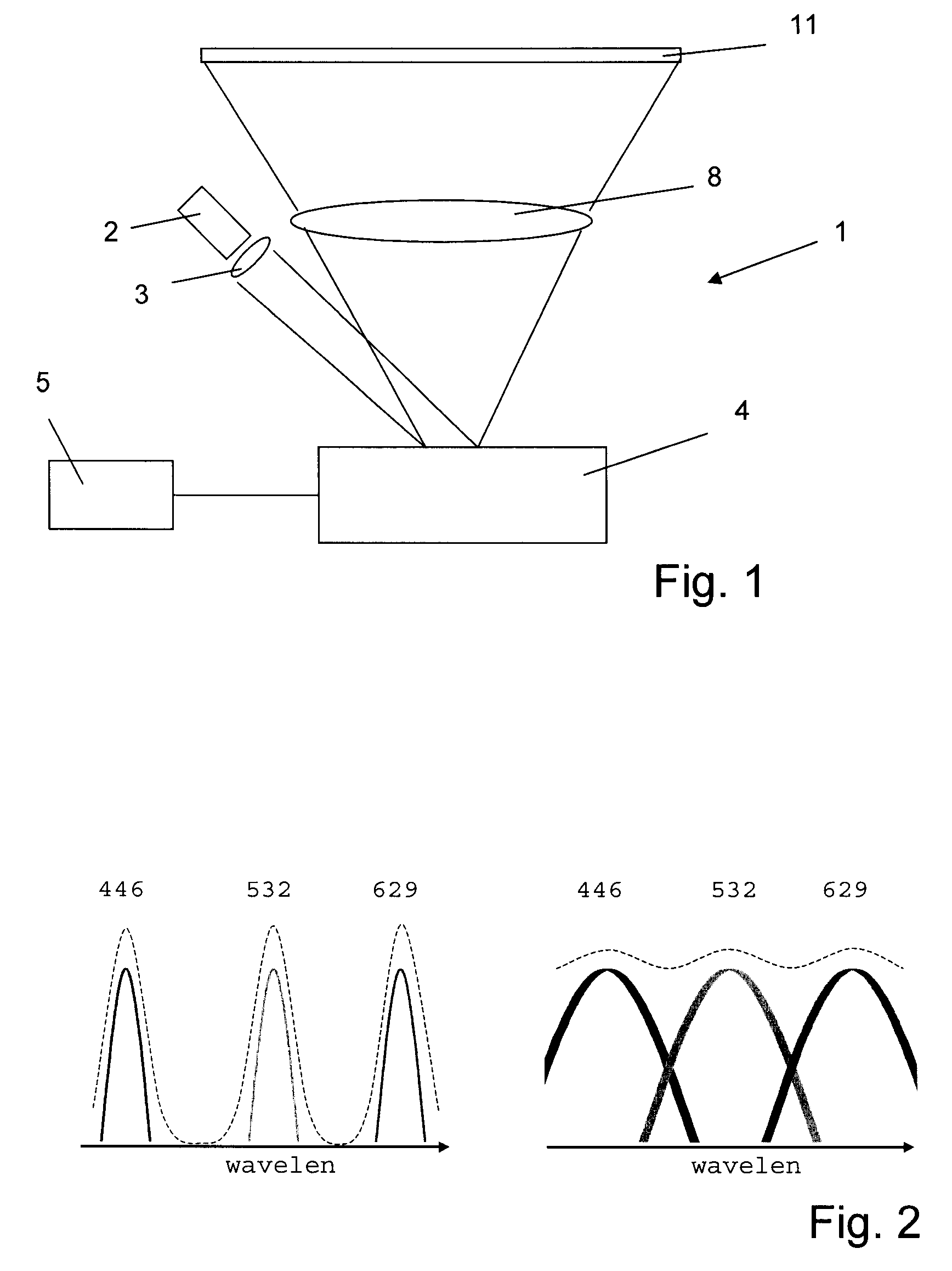
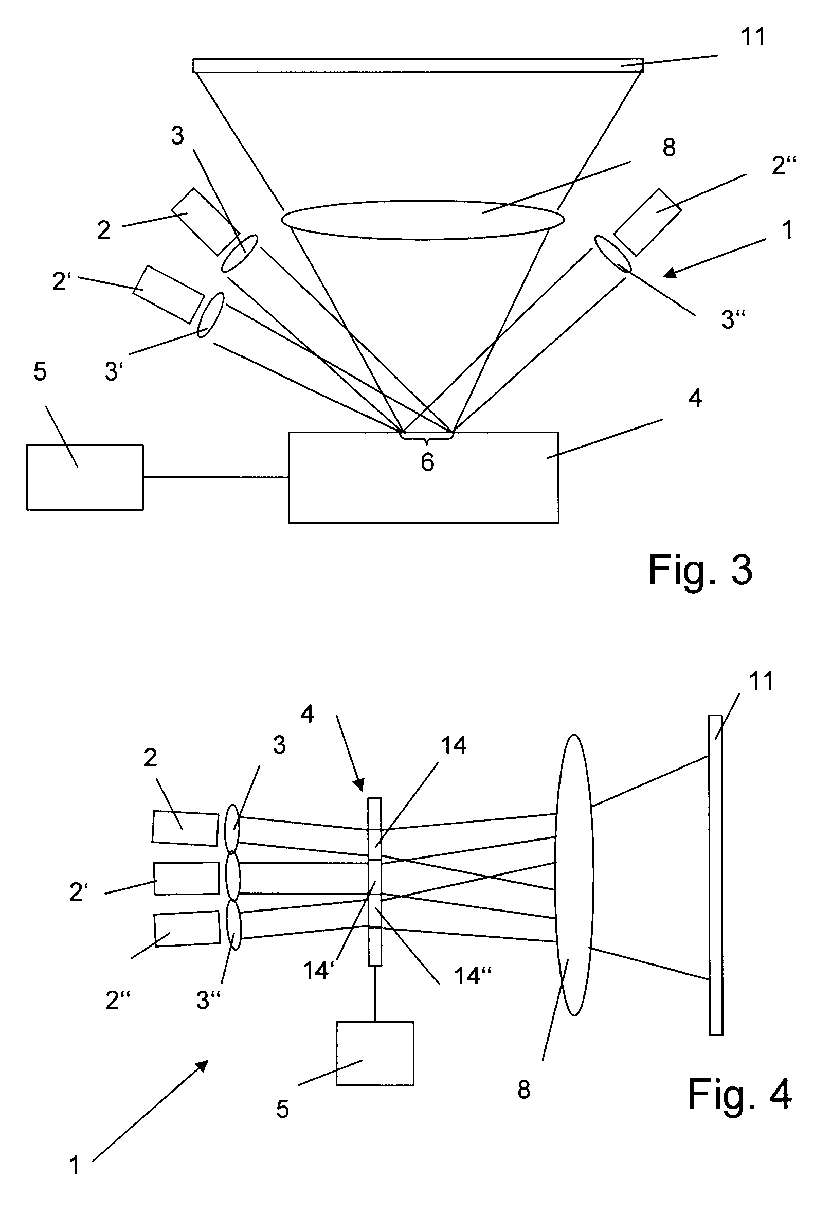
[0101]The display system shown in FIG. 1 includes a display apparatus 1 and a projection object having a display surface. In the shown embodiment, the projection object is a very schematically depicted screen 11 or panel.
[0102]The display apparatus 1 comprises a light source and a collimating optics 3. The light source includes a superluminescent light emitting diode 2.
[0103]Superluminescent light emitting diodes as such are known in the art. They rely on the principle that in a gain medium, population inversion is maintained by pumping and that due to this, spontaneously emitted radiation is amplified by stimulated emission. The radiation in the superluminescent light emitting diode may be guided by wave guiding means. In contrast to a laser, however, emitted radiation coming from the gain medium is not re-circulated to again enter the gain medium, thus, the gain medium is not in an optical resonator beam path. International patent application publication WO 2005/071 762, incorporated herein by reference, contains a discussion of possible means for preventing an SLED device from lasing, as well as a novel means for doing so.
[0104]The superluminescent light emitting diode (SLED) 2, in contrast to most prior art superluminescent light emitting diodes, emits visible light. For example, the SLED 2 may emit red or green or blue light. If blue light is to be emitted, the SLED contains a heterojunction of a GaN (or, to be more precise, InxGa1-xN with x between 0.05 and 0.2 for blue light—similar to the according value for blue lasers semiconductor material—and for green light a heterojunction of InxGa1-xN with x between 0.2 and 0.3, and for example Ga1-xInxP with x≅0.52 for red light. Other material systems suitable for generating, by the principle of stimulated emission, visible light are possible.
[0105]In a variant, the electromagnetic radiation emitted by the SLED is frequency converted, thus in such a variant, the light source next to at least one SLED also contains a frequency converter, for example a dye. Often, however, it is preferred to modulate the light directly emitted by the semiconductor device, thus the SLED.
[0106]The (optionally collimated) light emitted by the SLED light source impinges on a light modulating device 4. Such a light modulating device may be based on a technology known for modulating incident light for the purpose of providing an image to be displayed. For example, the light modulating device may be based on the principle known as digital light processing, which principle, for example, relies on a mechanism sometimes referred to as Digital Micro Mirror Device (DMD) mechanism, i.e. light modulation by a plurality of small mirrors the orientation and/or position of which may be controlled. The light-modulating device may as an alternative be based on another MEMS based mechanism such as Grating Light Valves or other. As yet other alternatives, the light modulating device may rely on the principle of Liquid Crystal Displays (LCDs) or on the principle of Electrically Switchable Bragg Gratings (ESBGs) or on another light modulation principle. The light modulating device may be of a reflection type—as illustrated in FIG. 1 or may be of a transmission type (for example if it is based on the LCD principle).
[0107]The light modulation device comprises an electronic control 5 schematically depicted in FIG. 1. The electronic control or parts thereof may optionally be integrated with the light modulation device 4 in a single unit such as a chip, or it may be separate therefrom.
[0108]The modulated light is directed to the projection surface by a projection optics 8, the projection optics preferably being a part of the display apparatus and for example—but not necessarily—being integrated with the other display apparatus components in a single casing.
[0109]Although a monochromatic display as illustrated in FIG. 1 lies within the scope of the invention, some advantages of the invention become most apparent for colored (i.e. multicolor) displays.
[0110]FIG. 2 illustrates in the left panel the spectra of a blue, a green and a red laser. As can be seen, the addition of the three spectra does not provide a complete coverage of the visible range but leaves gaps between the spectra of the three laser types.
[0111]The light emitted by the three laser sources may in principle be combined to generate white and any colored light. With this technique, it is ideally possible to complete the whole color gamut. This is what is normally done in laser display apparatus. Although the resulting image appears to be properly colored, most persons, however, would find it different from the image generated using a display system with filament lamps, such as xenon lamps.
[0112]Therefore, even though in principle all colors can be mixed by superposition of the contributions of the three lasers, the colors—and especially white light resulting from the mixture of all three colors—are perceived as not ideal. Rather, broadband light sources such as Xenon lamps have been observed to be more suitable to produce colors that users like, probably because the spectrum better resembles the black body spectrum.
[0113]Differently from lasers, sled devices are broadband light source, meaning that each single source can generate light over a large spectral range. Despite this, a SLED does not cover a spectrum as wide as the human eye can perceive, therefore is not a single source light generating device as a filament lamp. However, it is possible to design a system containing more than one SLED, with partially overlapping spectra that ensure an overall shape more similar to the back-body, as shown in the right panel in FIG. 2. As can be seen, the spectra of blue, green and red SLED light overlap in contrast to the according narrower bandwidth laser light. Therefore, blackbody radiation can be approximated by the superposition of the light emitted by three SLEDs much better than for lasers. Such an overlap is not feasible using laser devices, as it would require too many separate lasers.
[0114]However, the spectrum of a SLED is still narrow and well-defined enough for the number and spectral properties of the sled devices to be designed to have energy emitted only in the wavelength range suitable for human vision. This allows sparing UV and IR-filters required in conjunction with xenon lamps and improves the overall energy conversion efficiency of the system.
[0115]A first example of a multicolor display apparatus 1 according to the invention is illustrated in FIG. 3. The light source comprises three SLED devices 2, 2′, 2″ for the colors red, green, and blue. The active region of the SLED devices may comprise the semiconductor material compositions mentioned above. Through collimation optics 3, 3′, 3″ the light emitted by the SLEDs projected on the light modulating device 4. The light with the image information in it prepared by the modulation device is then focused on the display surface 11 to be illuminated.
[0116]The light modulating device in accordance with the design as shown in FIG. 3 features only one light modulating unit (thus only one unit that creates a pre-image to be imaged onto the display surface). The light portions originating from the plurality of SLEDs are all projected onto the same light modulating unit area 6. Therefore, in this design the SLEDs and the light-modulating device have to be operated in time-division multiplexing with a sufficient swapping frequency of, for example, at least 200 Hz so that arbitrary color impressions can be generated on the display surface.
[0117]The light modulating device 4 shown in FIG. 4 is also of the reflection type, but, as for the above-shown embodiment, the concept would also work for transmission type light modulating devices.
[0118]The multicolor display apparatus 1 according to FIG. 4 comprises a light modulating device of the transmission type, i.e. the light modulating device comprises at least one unit through which light is transmitted and thereby modulated to provide a pre-image. More concretely, the light modulating device 4 of the multicolor display apparatus comprises a plurality of transmission type light modulating units 14, 14′, 14″. The light modulating units may for example be liquid crystal display (LCD) units of the type that as such is known in the art. The number of light modulating units corresponds to the number of colors provided by SLED devices of the light source (for example three for the colors red, green and blue), and, since preferably exactly one SLED device or group of SLED devices is present per color, in the shown embodiment also corresponds to the number of SLED devices 2, 2′, 2″. The projection optics 8 in the shown embodiment has the additional functionality (in addition to imaging the pre-images onto the display surface) of uniting the light proportions originating from the different SLED devices. This may for example be done by an appropriate arrangement of beam splitters (not shown).
[0119]For all embodiments of the present invention, it would also be possible to provide more than one SLED device per color; the light source would then comprise at least one group of a plurality of SLED devices with the same emission spectra.
[0120]Also, the embodiment of the display apparatus 1 depicted in FIG. 5 comprises a plurality of SLED devices 2, 2′, 2″ and dedicated collimation optics 3, 3′, 3″. In contrast to the embodiment of FIG. 4, the light modulating device is not of the transmission type but of the reflection type, similar to the one shown in FIG. 1. The light modulating device comprises three light modulating units 14, 14′, 14″, each operable to define a single color pre-image. The projection optics 8 is operable to image the three pre-images onto the projection surface in a manner that the three pre-images are superposed one on another so that a colored image covering the full gamut is created. The projection optics in the shown arrangement includes a dichroic (or, to be precise, trichroic) prism 21. The light modulating units 14, 14′, 14″ may, as illustrated, be spatially separated or may alternatively be arranged on a common carrier element.
[0121]In the previously shown embodiments the SLED devices were shown as single devices separate from each other, each, for example, with its own contact means for supplying an appropriate current and each, for example, with its own casing (if any). This need not be the case. Rather, multiple SLEDs can be integrated and, for example, be arranged on a common substrate. Such monolithically integrated SLEDs may be essentially identical (all emit the same color) or may include layers of different semiconductor material compositions so that they emit at different wavelengths. For example, a red, green, and blue SLED may be on a common substrate and may constitute a multicolor light source as used for the embodiments of FIGS. 4 and 5 or other multicolor display embodiments of the invention.
[0122]FIG. 6 very schematically illustrates an example of a light source in which a plurality of SLED devices is integrated on a common substrate. The three SLEDs are defined waveguides formed by ridges 22, 22′, 22″. In case the three SLEDs emit light of different spectral compositions, the layer structure (not shown) forming the necessary PN junction is horizontally structured, i.e. comprises regions of different material compositions or potentially a composition gradient as a function of the “horizontal” (i.e. perpendicular to the layers) position (of the x position in the illustrated embodiment). Such horizontal structuring may be achieved by means of masks or other means as such known in the art for structuring semiconductor devices. The three light fields 23, 23′, 23″ (for example of the red, green and blue light) formed under the ridges are also illustrated in the Figure.
[0123]With reference to FIGS. 7-9 very schematically different set-ups including an apparatus according to the invention are illustrated.
[0124]FIG. 7 illustrates a front projection system where an apparatus according to the invention 31 that incorporates the projection optics comprises a casing and is a possibly transportable device with a single power cable input and power supply unit (not illustrated), and further comprising a data interface for video data to be supplied to the electronic control. The front projection apparatus may, for example, be used as a video or data projector.
[0125]FIG. 8 illustrates a rear projection system where an apparatus according to the invention includes the projection surface 33. The projection surface includes a diffuser of light incident from the rear side. Often, the light emitted by a projection unit 31 that includes the light source and light modulating device as well as some optics is re-directed within the apparatus by re-directing and imaging means 32 that may include an appropriate number of mirrors, lenses and other passive optical components. An apparatus of the kind depicted in FIG. 8 may, for example, be used as a color television set or a monitor.
[0126]In FIG. 9, a head-up display is illustrated very schematically, where the apparatus according to the invention is a projection unit 31 that includes the light source and light modulating device as well as some optics. The image is projected via an at least partially reflecting element 41—such as windshield, a transparent portion of safety glasses or other eyeglasses, a display surface or other—to the human eye 42. In such an embodiment, the imaging functionality of the projection unit 31 may be such as to image the desired image onto the at least partially reflecting element 41 so that the user sees the image when she/he focuses onto the element 41. As an alternative, the projection unit may include the functionality of a virtual retinal display (retinal scan display) device, where the displayed information is directly imaged onto the retina, so that the user does not have to focus on the screen but gets the impression that the image is located at a far distance (for example at infinite distance, so that the image is focused when the user focuses on objects that are far away, for example, while driving or flying.). The technique of a retinal scan display which can also be used in conjunction with reflecting elements 41 that are very close to the eye as such is known and will not be described in any more detail here.
[0127]Various other embodiments may be envisaged without departing from the scope and spirit of the invention.