
Ink jet recording head and production process thereof

a technology of recording head and ink jet, which is applied in the direction of printing, etc., can solve the problems of affecting the ejection characteristics of ink, the inside of the ink chamber is subjected to high temperatures, and the corrosion of metal surfaces, so as to achieve the effect of reducing the siz

Active Publication Date: 2008-11-06
CANON KK
View PDF11 Cites 17 Cited by
  • Summary
  • Abstract
  • Description
  • Claims
  • Application Information

AI Technical Summary

Benefits of technology

[0014]A principal object of the present invention is to provide a recording head substrate which is provided with a testing (inspecting) electrode for an anti-cavitation film and is reduced in size.

Problems solved by technology

In such a recording head, the heat generating elements generate heat, so that the inside of the ink chamber is subjected to high temperatures.
Further, when bubbles generated by heating collapse, there is a possibility of an occurrence of corrosion at a metal surface by the action of water hammer.
For this reason, mutual interference between respective ejection outlets can occur to impair ink ejection characteristics such as an ink ejection speed, an amount of ink ejection, and so on.
However, this method involves problems of realization of high driving frequency for increasing the number of time-sharing drive block and accuracy of a current wiring process for increasing the number of individual divided lines, as limiting factors.
Further, at a portion above the heat generating element array portion 2101, there is a possibility of an occurrence of corrosion by the action of water hammer during collapse of bubbles generated by heating.
However, as shown in FIG. 6, when the plated common power source line is disposed between these anti-cavitation films, it is impossible to connect these anti-cavitation films with the connecting line.
As a result, this method also cannot avoid the large-size substrate.

Method used


Image

  • Ink jet recording head and production process thereof
  • Ink jet recording head and production process thereof
  • Ink jet recording head and production process thereof

Examples


Embodiment Construction

[0032]Hereinbelow, embodiments of the present invention will be described with reference to the drawings.

[Recording Head Substrate]

[0033]An embodiment of a recording head substrate according to the present invention will be described.

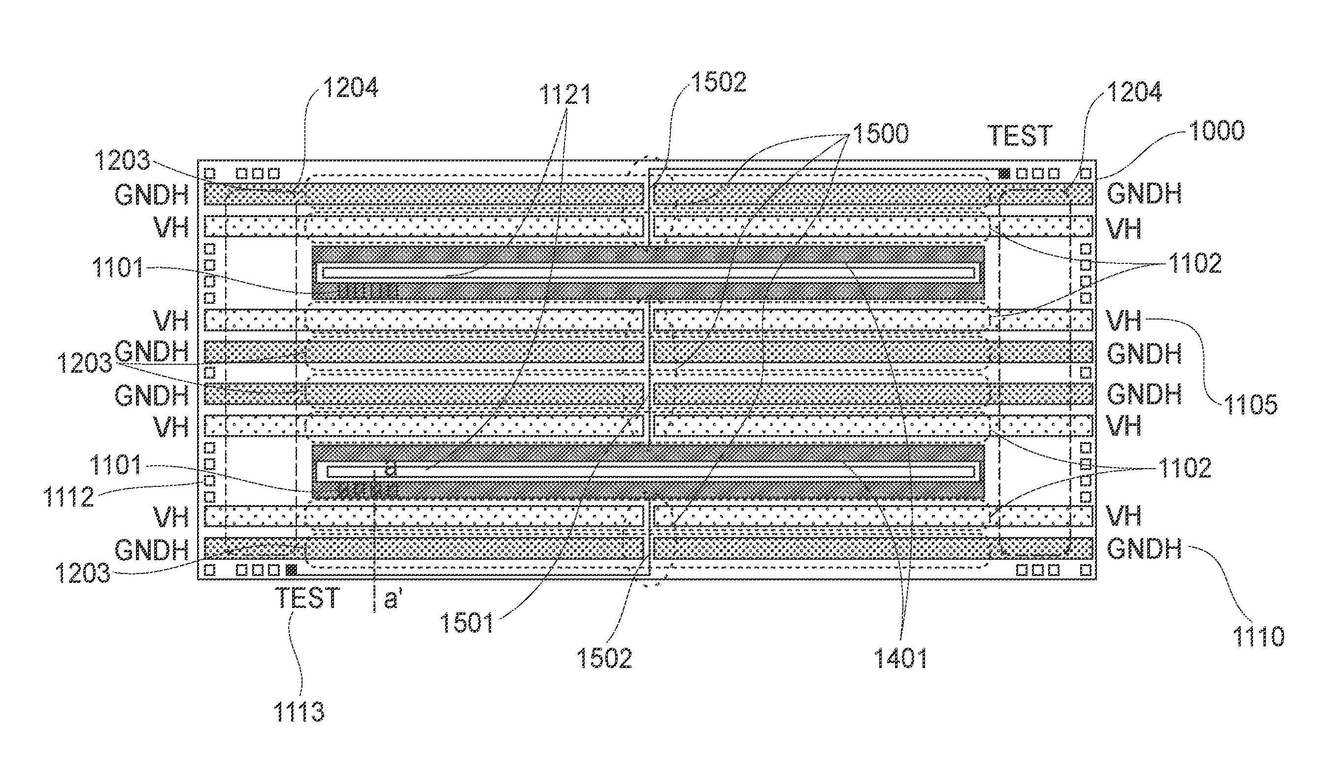
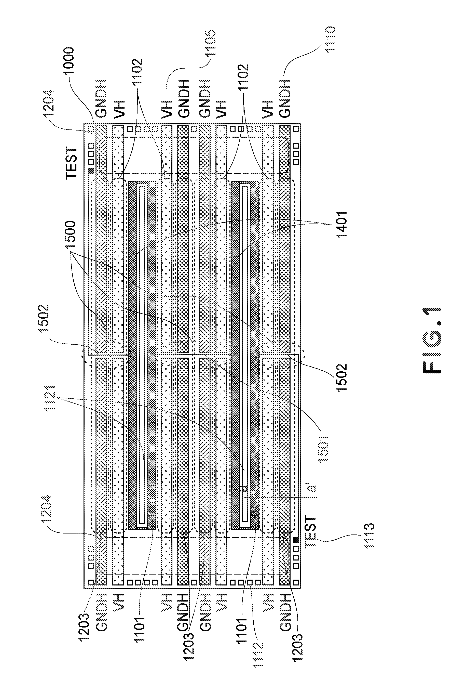
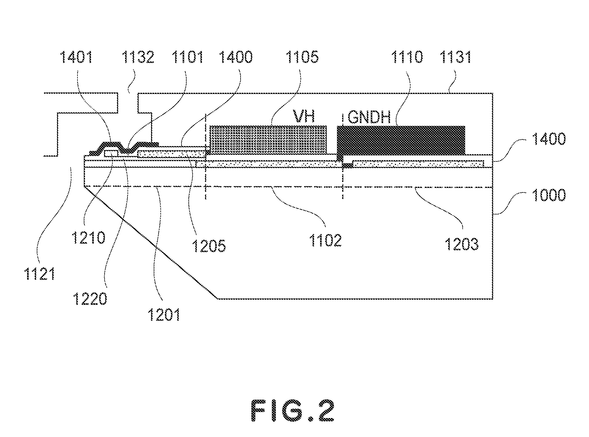
[0034]FIG. 1 is a schematic view showing a layout of the embodiment of the recording head substrate of the present invention. FIG. 2 is a schematic sectional view of the recording head substrate taken along a-a′ line indicated in FIG. 1.

[0035]With respect to the recording head substrate, a multi-layer wiring technique is employed. (Wiring) lines for connecting respective constitutional elements are interposed between insulating films (protecting films) to provide a multi-layer structure. Further, the respective (upper and lower) lines are mutually connected by a through hole (an opening of the insulating film) at an arbitrary point on the substrate to form a circuit.

[0036]A recording device substrate 1000 includes heat generating elements 1101, transist...


PUM


Abstract

An ink jet recording element substrate includes a substrate; an ejection outlet array for ejecting ink; a heat generating element array comprising a plurality of heat generating elements for generating ejection energy for ejecting the ink from the ejection outlet array; a protecting film, comprising protecting portions, for protecting the heat generating element array; a common line, disposed along a side of the heat generating element array, for supplying electric power for driving the heat generating elements, and being divided into at least two portions by a line perpendicular to the heat generating element array; a testing electrode for testing a function of the protecting film; and an externally connecting electrode, disposed at an end of the substrate, for externally supplying electric power to the common line; wherein the ink jet recording element substrate further includes, in an area between the portions of the common line, a connecting line for electrically connecting the protecting portions of the protecting film disposed to sandwich the common line and a lead line for electrically connecting the protective film and the testing electrode.

Description

FIELD OF THE INVENTION AND RELATED ART[0001]The present invention relates to an ink jet recording head substrate, an ink jet recording head including the ink jet recording head substrate, and a recording apparatus including the ink jet recording head.[0002]In an ink jet recording head using heat generating elements, the heat generating elements are provided in an ink chamber as a part of an ink flow path and an electric pulse as a recording signal is supplied to the heat generating elements to generate heat. The ink jet recording head ejects minute ink droplets from minute ejection outlets by utilizing bubble pressure of liquid ink bubbled (boiled) due to heat energy by the heat generation, thus effecting recording with respect to a recording medium. Such a recording head generally includes ink ejection outlets for ejecting ink droplets and a supplying system containing a flow path for supplying ink to the ejection outlets.[0003]In such a recording head, the heat generating elements...

Claims


Application Information

Patent Timeline
IPC IPC(8): B41J2/01B41J2/165B41J2/14
CPCB41J2/14072B41J2/14129
Inventor TAKEUCHI, SOUTAIMANAKA, YOSHIYUKIHATSUI, TAKUYAYAMAGUCHI, TAKAAKIMATSUI, TAKAHIROKUBO, KOUSUKE
Owner CANON KK
Learn More