
System for Detecting Image Abnormalities

Active Publication Date: 2008-11-06
PICTOMETRY INTERNATIONAL CORPORATION
View PDF118 Cites 38 Cited by
  • Summary
  • Abstract
  • Description
  • Claims
  • Application Information

AI Technical Summary

Problems solved by technology

When capturing images with a digital sensor, a variety of abnormalities such as elevated sensor noise levels, streaks, blooms or smears can be formed within the captured image.
Such abnormalities can be caused by malfunctions of the image capture device, or by the external environment.
This typically ruins a part of the image and causes the manual rescheduling at a later time / date of another image of the same area to be taken.
Because the abnormality is not detected until after the airplane has landed and the images are processed, the re-taking of another image of the same area typically results in time delays and costly re-flights.

Method used


Image

  • System for Detecting Image Abnormalities
  • System for Detecting Image Abnormalities
  • System for Detecting Image Abnormalities

Examples


Embodiment Construction

[0031]Before explaining at least one embodiment of the invention in detail, it is to be understood that the invention is not limited in its application to the details of construction, experiments, exemplary data, and / or the arrangement of the components set forth in the following description or illustrated in the drawings. The invention is capable of other embodiments or being practiced or carried out in various ways. Also, it is to be understood that the phraseology and terminology employed herein is for purposes of description and should not be regarded as limiting.

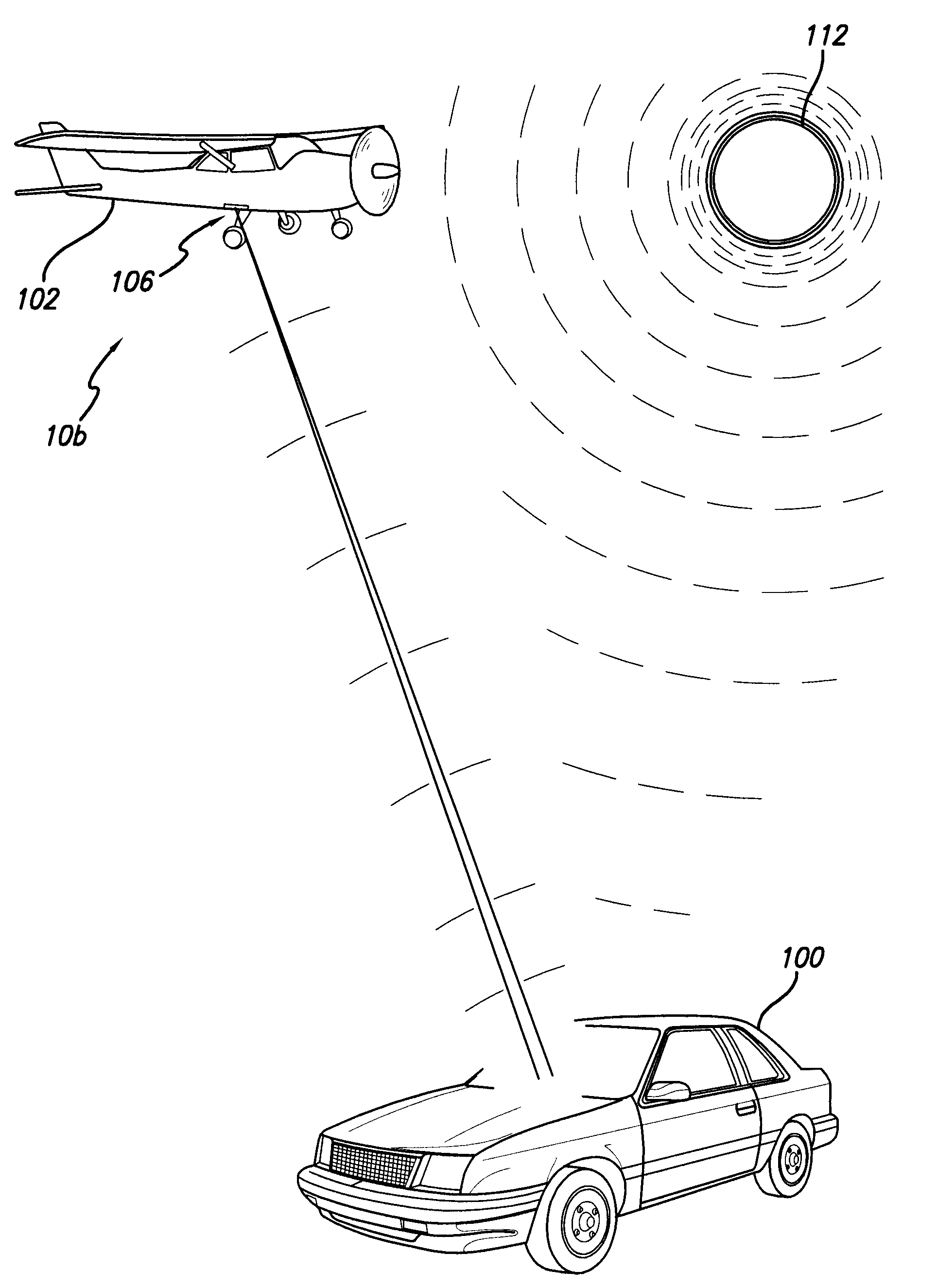
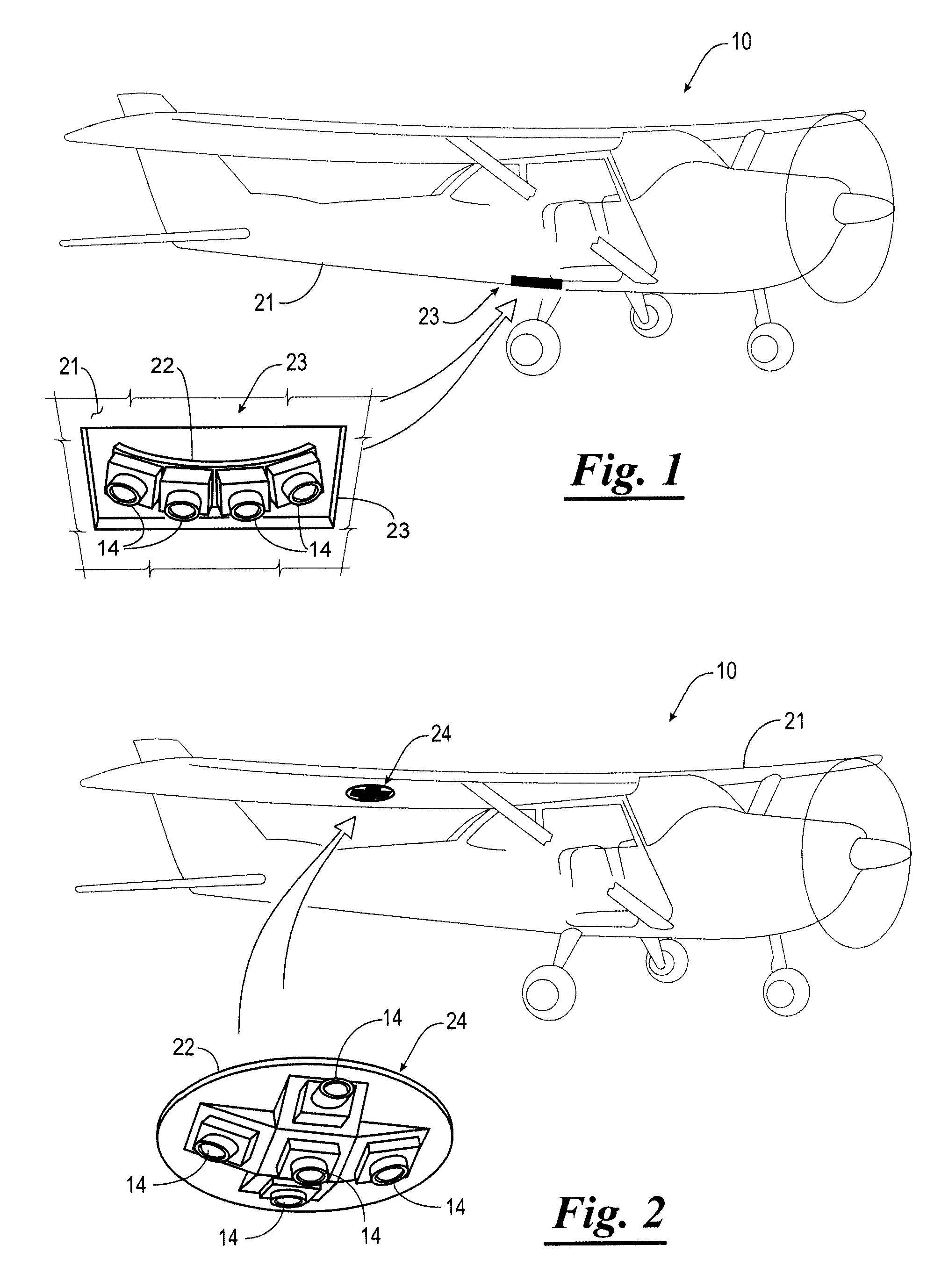
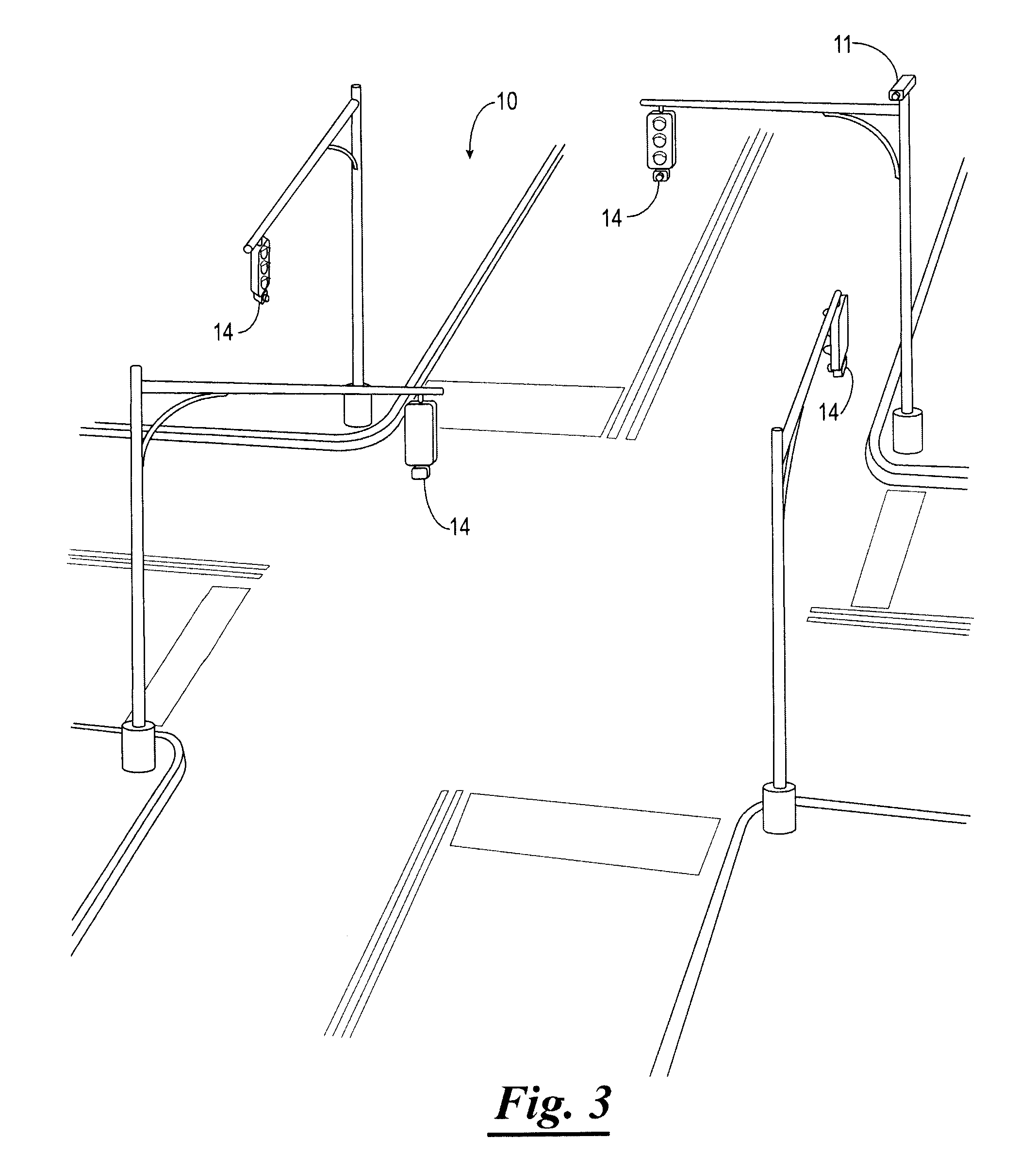
[0032]Referring to the drawings, and in particular to FIGS. 1, 2 and 3, shown therein and designated by a reference numeral 10 is an image capture system constructed in accordance with the present invention. The image capture system 10 is typically used for capturing aerial images as shown in FIGS. 1 and 2. However, while the image capture system 10 is extremely useful for aerial imaging, it has numerous other applicati...


PUM


Abstract

An image capture system for capturing images of an object, the image capture system comprising a moving platform such as an airplane, one or more image capture devices mounted to the moving platform, and a detection computer. The image capture device has a sensor for capturing an image. The detection computer executes an abnormality detection algorithm for detecting an abnormality in an image immediately after the image is captured and then automatically and immediately causing a re-shoot of the image. Alternatively, the detection computer sends a signal to the flight management software executed on a computer system to automatically schedule a re-shoot of the image. When the moving platform is an airplane, the detection computer schedules a re-shoot of the image such that the image is retaken before landing the airplane.

Description

CROSS-REFERENCE TO RELATED APPLICATIONS[0001]The present patent application claims priority to the provisional patent application identified by U.S. Ser. No. 60 / 926,985, the entire content of which is hereby incorporated herein by reference.STATEMENT REGARDING FEDERALLY SPONSORED RESEARCH AND DEVELOPMENT[0002]Not Applicable.BACKGROUND OF THE INVENTION[0003]As background, in the remote sensing / aerial imaging industry, imagery is used to capture views of a geographic area and to be able to measure objects and structures within the images as well as to be able to determine geographic locations of points within the image. These are generally referred to as “geo-referenced images” and come in two basic categories:[0004]Captured Imagery—these images have the appearance they were captured by the camera or sensor employed.[0005]Projected Imagery—these images have been processed and converted such that they confirm to a mathematical projection.[0006]All imagery starts as captured imagery, bu...

Claims


Application Information

Patent Timeline
IPC IPC(8): G06K9/00
CPCG01C11/02G06T7/0004G06T2207/10032G06T2207/30168G06T2207/30181
Inventor GIUFFRIDA, FRANKSCHULTZ, STEPHEN
Owner PICTOMETRY INTERNATIONAL CORPORATION
Learn More