
Apparatus and Method for Rapid Microscopic Image Focusing

a technology of rapid microscopic image and apparatus, applied in the field of apparatus and methods for rapid microscopic image focusing, can solve the problems of large unsupervised manner, low impact of such interactive systems on routine workflow, and high cost of automatic systems

Active Publication Date: 2008-11-06
TRIPATH IMAGING INC
View PDF12 Cites 44 Cited by
  • Summary
  • Abstract
  • Description
  • Claims
  • Application Information

AI Technical Summary

Benefits of technology

This approach enables rapid and cost-effective focusing across various magnifications and focal planes, reducing scanning time and improving image quality by determining the optimal focus level through contrast evaluation, thus enhancing the efficiency of microscopic image acquisition.

Problems solved by technology

If properly configured, interactive systems are relatively fast and cost efficient, but the impact of such interactive systems on routine workflow is relatively small.
Automatic rare event detection devices are typically set up in a way that the whole analysis of the slides is done by the system in a totally unsupervised manner, from the loading of the slides onto the scanning stage to the final reporting of the results.
However, such automatic systems are normally quite expensive, so that a relatively high annual volume of slides must be processed to cost-justify the acquisition of such a device.
This mode of operation leads to impractically large scanning times. A progressive scan mode may be one alternative to gain slide scanning speed, but such a mode requires a specific focusing strategy capable of cooperating and functioning with the continuous scanning motion.
Certain types of applications require the recapture of numerous objects of interest and, as such, the amount of time spent for this task is critical.
However, such a camera assembly is optimized for a particular magnification and cannot readily be used for a different magnification setting.
However, such a method presents two potential drawbacks: (i) the equipment costs tend to be very expensive; and (ii) the size of the 3D volume of the image (number of planes, distance between the planes) may be limited by hardware constraints.
However, no use of the system in a continuous motion image acquisition procedure is disclosed.

Method used


Image

  • Apparatus and Method for Rapid Microscopic Image Focusing
  • Apparatus and Method for Rapid Microscopic Image Focusing
  • Apparatus and Method for Rapid Microscopic Image Focusing

Examples


Embodiment Construction

[0050]The present inventions now will be described more fully hereinafter with reference to the accompanying drawings, in which some, but not all embodiments of the inventions are shown. Indeed, these inventions may be embodied in many different forms and should not be construed as limited to the embodiments set forth herein; rather, these embodiments are provided so that this disclosure will satisfy applicable legal requirements. Like numbers refer to like elements throughout.

I Oscillating Focusing

[0051]Embodiments of the present invention are directed to apparatuses and methods for rapid microscopic image focusing that can be used for both static high-resolution object recapture and for continuous motion high-resolution image focusing.

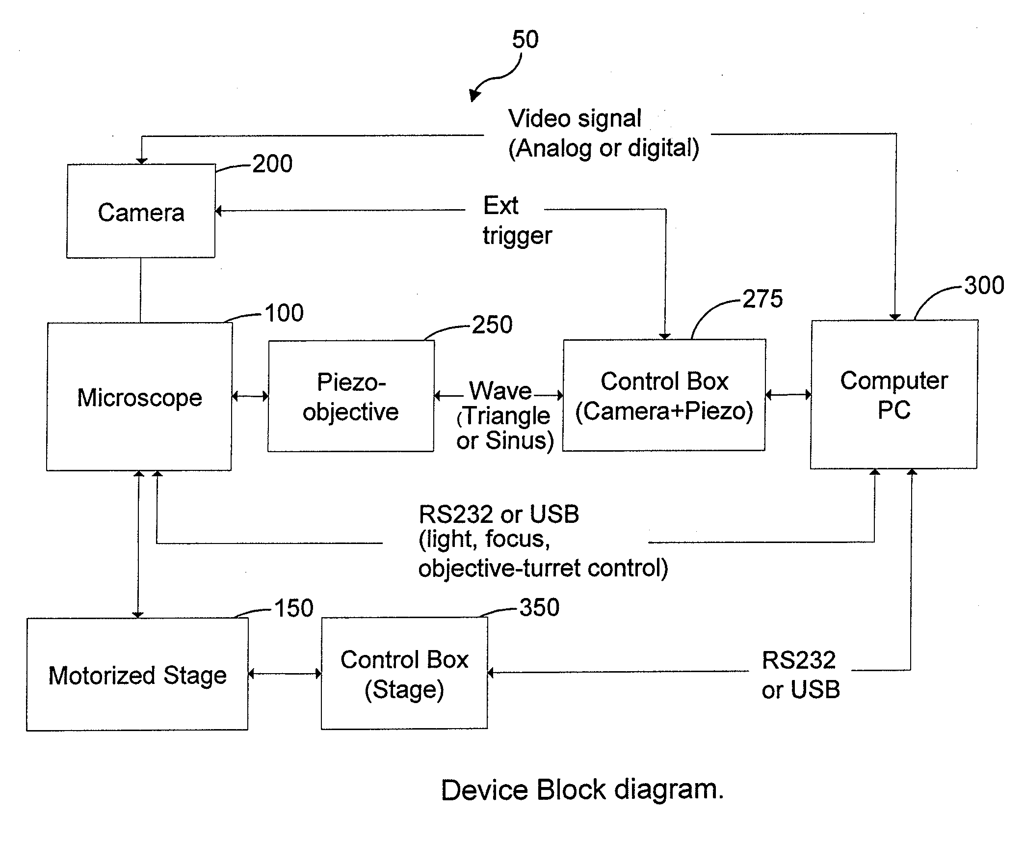
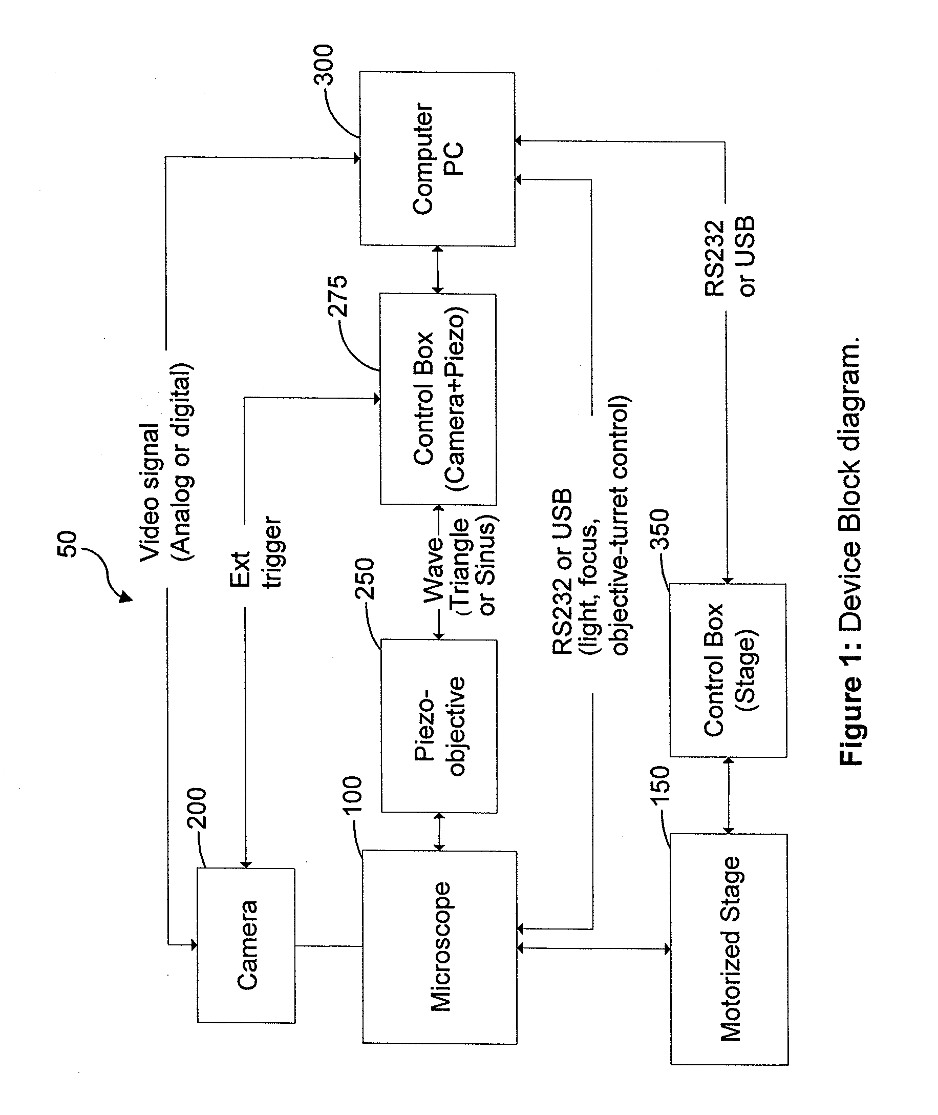
[0052]One embodiment of the present invention implements an integrated system 50 as shown, for example, in FIG. 1, that includes a microscope 100 with built-in automation functionalities (e.g., a Zeiss Axiolmager), a motorized stage 150 for the micro...


PUM


Abstract

A method of capturing a focused image of a continuously moving slide / objective arrangement is provided. A frame grabber device is triggered to capture an image of the slide through an objective at a first focus level as the slide continuously moves laterally relative to the objective. Alternatingly with triggering the frame grabber device, the objective is triggered to move to a second focus level after capture of the image of the slide. The objective moves in discrete steps, oscillating between minimum and maximum focus levels. The frame grabber device is triggered at a frequency as the slide continuously moves laterally relative to the objective so multiple images at different focus levels overlap, whereby a slide portion is common to each. The image having the maximum contrast value within overlapping images represents an optimum focus level for the slide portion, and thus the focused image. Associated apparatuses and methods are also provided.

Description

CROSS-REFERENCE TO RELATED APPLICATIONS[0001]This application is a divisional application of U.S. application Ser. No. 11 / 425,605, filed Jun. 21, 2006, which claims the benefit of U.S. Provisional Application No. 60 / 692,761, filed Jun. 22, 2005, which are incorporated by reference herein in their entirety.BACKGROUND OF THE INVENTION[0002]1. Field of the Invention[0003]The present invention relates to apparatuses and methods for the rapid focusing and acquisition of images of objects and areas of interest on a microscope slide.[0004]2. Description of Related Art[0005]Microscopic analysis is a widely used tool for research and routine evaluations, particularly in the field of cellular biology, cytology and pathology. Tissue samples and cell preparations are visually inspected by pathologists under several different conditions and test procedures, through the use of a microscope. Based on such a visual inspection by the pathologist, determinations concerning the tissue or cellular mate...

Claims


Application Information

Patent Timeline
Patent Type & Authority Applications(United States)
IPC IPC(8): G06K9/00
CPCG02B21/244G06T5/50G06T2207/10056G06T2207/30024G06V20/693
Inventor KRIEF, BRUNOMARCELPOIL, RAPHAEL
Owner TRIPATH IMAGING INC
Learn More