Complex index refraction tomography with sub lambda/6-resolution

a technology of complex index and refraction tomography, applied in the field of complex index refraction tomography with sub lambda/6resolution, can solve the problems of reducing the effective spectrum of the wavefield, and meeting known limitations

Active Publication Date: 2013-03-07
ECOLE POLYTECHNIQUE FEDERALE DE LAUSANNE (EPFL)
View PDF4 Cites 37 Cited by
  • Summary
  • Abstract
  • Description
  • Claims
  • Application Information

AI Technical Summary

Problems solved by technology

High resolution imaging of microscopic objects based on waves propagating in the far field meets known limitations due to their limited spectrum associated with their limited energy.
These limitations of the spectrum apply in the time as well as in the spatial domain.
The further limitations are due to instrumental considerations: the effective spectrum of the wavefield is further diminished by the configuration of the instrument collecting the emitted or scattered wave in a cone intercepting the pupil of the microscope objective (MO).
In many situations, the problem appears however as ill posed.
It is computer intensive and the applications in optical microscopy appear quite limited.
This technique, also designated by: transport intensity techniques: TIT, provides quantitative phase imaging, but has the drawback to be based on the computation of the derivative or gradient of the wavefield intensity, introducing thereby a high sensitivity to noise and artifacts.
Coherently illuminated imaging systems suffer from an inferior lateral resolution compared to its incoherent counterpart.
However, the scaling of resolution to high-NA systems introduces strong diffraction and aberration sensitivity.
The use of MO under non-design rotation conditions introduces additional experimental aberrations that may further degrade resolution.
Unfortunately, the theory of diffraction tomography cannot correct for these conditions since it is based on direct filtering by an ideal Ewald sphere.
Generally, these methods require to alter the experimental setup with additional modifications e.g. gratings or mechanically moving parts, giving rise to practical issues.

Method used


Image

  • Complex index refraction tomography with sub lambda/6-resolution
  • Complex index refraction tomography with sub lambda/6-resolution
  • Complex index refraction tomography with sub lambda/6-resolution

Examples


Embodiment Construction

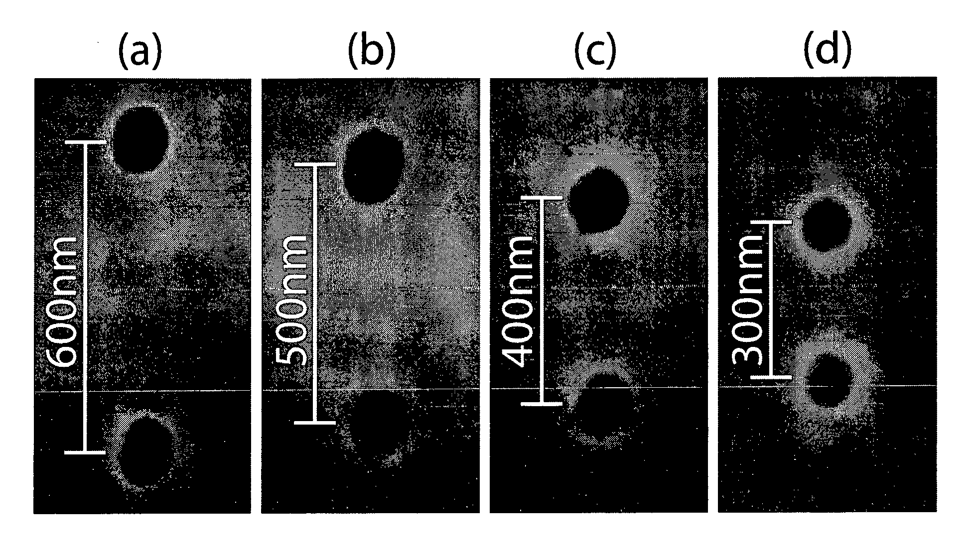
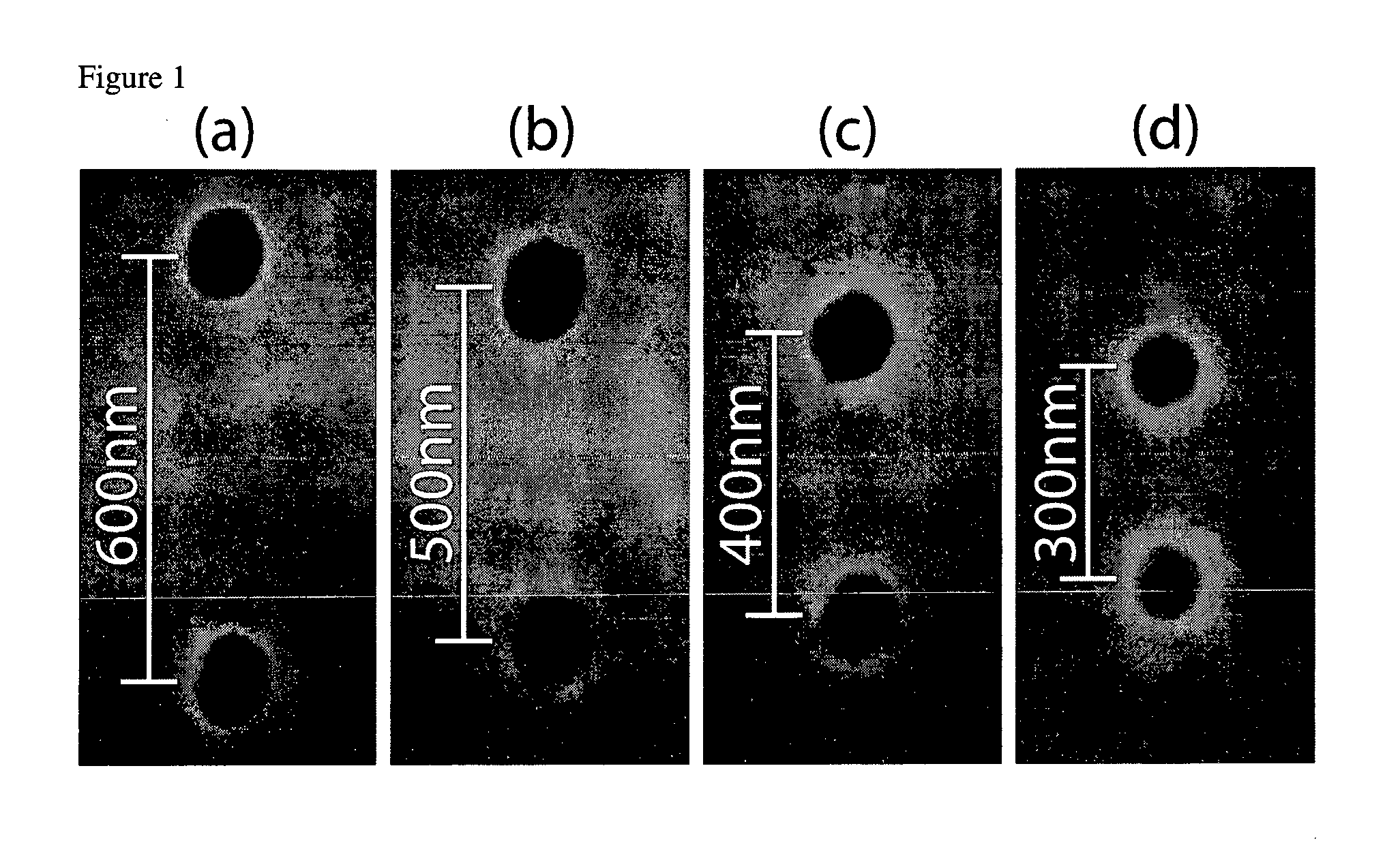
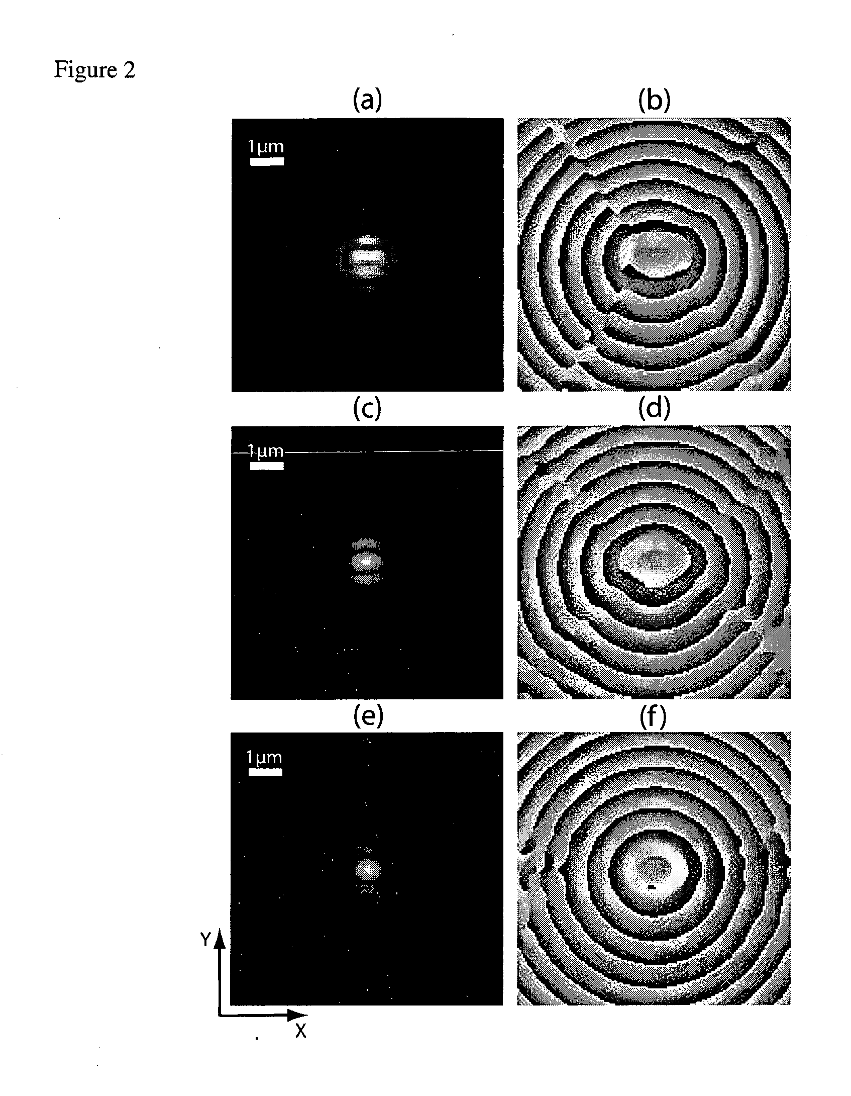
[0045]For the first time to our knowledge, it is demonstrated in the present invention that a method based on the information content available from the phase as well as from the amplitude of the complex field scattered by the observed specimen, can deliver super-resolution microscopic images of a specimen, i.e. images with a resolution beyond the Rayleigh limit of the microscope. These assertion is demonstrated by developing the theory and giving the experimental evidence that such a resolution improvement can be achieved on an optical microscope specially adapted or modified to measure the complex wavefield of the wave radiated by the specimen, and where the wavefront is reconstructed according to the any methods developed to achieve quantitative phase microscopy: defocused imaging, modified DIC, Shack-Hartmann wavefront analyzer or any analyzer derived from a similar principle, such as multi-level lateral shearing interferometers or common-path interferometers, or devices that co...


PUM


Abstract

The present invention discloses a method to improve the image resolution of a microscope. This improvement is based on the mathematical processing of the complex field computed from the measurements with a microscope of the wave emitted or scattered by the specimen. This wave is, in a preferred embodiment, electromagnetic or optical for an optical microscope, but can be also of different kind like acoustical or matter waves. The disclosed invention makes use of the quantitative phase microscopy techniques known in the sate of the art or to be invented. In a preferred embodiment, the complex field provided by Digital Holographic Microscopy (DHM), but any kind of microscopy derived from quantitative phase microscopy: modified DIC, Shack-Hartmann wavefront analyzer or any analyzer derived from a similar principle, such as multi-level lateral shearing interferometers or common-path interferometers, or devices that convert stacks of intensity images (transport if intensity techniques: TIT) into quantitative phase image can be used, provided that they deliver a comprehensive measure of the complex scattered wavefield. The hereby-disclosed method delivers superresolution microscopic images of the specimen, i.e. images with a resolution beyond the Rayleigh limit of the microscope. It is shown that the limit of resolution with coherent illumination can be improved by a factor of 6 at least. It is taught that the gain in resolution arises from the mathematical digital processing of the phase as well as of the amplitude of the complex field scattered by the observed specimen. In a first embodiment, the invention teaches how the experimental observation of systematically occurring phase singularities in phase imaging of sub-Rayleigh distanced objects can be exploited to relate the locus of the phase singularities to the sub-Rayleigh distance of point sources, not resolved in usual diffraction limited microscopy. In a second, preferred embodiment, the disclosed method teaches how the image resolution is improved by complex deconvolution. Accessing the object's scattered complex field—containing the information coded in the phase—and deconvolving it with the reconstructed complex transfer function (CTF) is at the basis of the disclosed method. In a third, preferred embodiment, it is taught how the concept of “Synthetic Coherent Transfer Function” (SCTF), based on Debye scalar or Vector model includes experimental parameters of MO and how the experimental Amplitude Point Spread Functions (APSF) are used for the SCTF determination. It is also taught how to derive APSF from the measurement of the complex field scattered by a nanohole in a metallic film. In a fourth embodiment, the invention teaches how the limit of resolution can be extended to a limit of λ/6 or smaller based angular scanning. In a fifth embodiment, the invention teaches how the presented method can generalized to a tomographic approach that ultimately results in super-resolved 3D refractive index reconstruction.

Description

1 BACKGROUND OF THE INVENTION[0001]High resolution imaging of microscopic objects based on waves propagating in the far field meets known limitations due to their limited spectrum associated with their limited energy. These limitations of the spectrum apply in the time as well as in the spatial domain. These bandwidth limitations introduce naturally a band-stop or band rejection filter in the spatial frequency domain (SFD). The occupation of the SFD is therefore limited to an area or most often a disk of diameter twice as large as the bandwidth of the optical system bandwidth. This problem has been described in basic textbooks such as {Goodman, 1968}. Due to the band-stop BS described earlier: kx, kyεBS, the angular spectrum: complex amplitude as a function of the unit vector ŝ(kx / k,ky / k,√{square root over (k2−kx2−ky2)} / k) of the beam diffracted by the object. The components ŝx and ŝy are included in the unit disk in the x-y plane. The further limitations are due to instrumental con...

Claims


Application Information

Patent Timeline
Patent Type & Authority Applications(United States)
IPC IPC(8): G01B9/021
CPCG02B21/365G03H2001/005
Inventor COTTE, YANNPAVILLON, NICOLASDEPEURSINGE, CHRISTIAN
Owner ECOLE POLYTECHNIQUE FEDERALE DE LAUSANNE (EPFL)
Why Eureka
Try Eureka